Skip to content
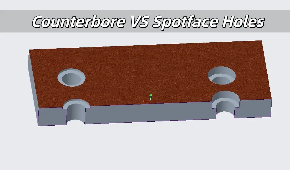
 In machining, CNC programming, and engineering drawing, counterbore holes and spotface holes are both used for fastener installation, but differ significantly in core functions, processing requirements, and application scenarios. Accurately distinguishing them is key to ensuring workpiece assembly accuracy, surface quality, and processing efficiency, which will be systematically decomposed below.
What is a Counterbore?
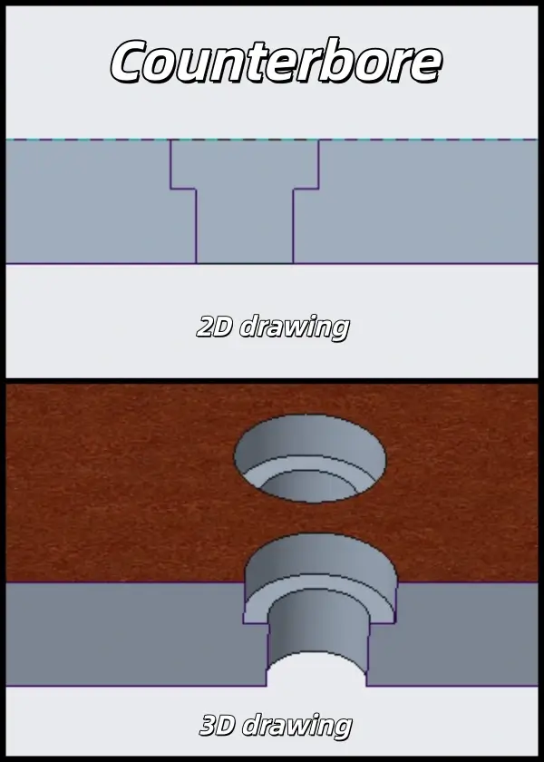
A counterbore hole is a stepped structure with a cylindrical groove of clear depth, processed by special tooling. Its core purpose is to accommodate fastener heads (e.g., bolts, screws), keeping them completely below the workpiece surface for flatness and anti-interference. It consists of a base through hole and an upper groove (larger in diameter), with groove depth matching fastener head height, belonging to precision machining.
Counterbore in Engineering Drawings
Counterbore dimensioning must be complete, indicating base hole diameter/depth, groove diameter/depth, and coaxiality. Follow the sequence: drill the base hole first, then the counterbore. For mass production, tolerances are specified (±0.1mm for depth, ±0.2mm for diameter) to ensure consistency, and coaxiality is required to avoid installation skew.
Counterbore Symbol
The counter bore symbol (c bore symbol) is internationally denoted as “⌴”, or abbreviated as “CB”. The marking format is “symbol + groove diameter × groove depth + base hole parameters” (e.g., “⌴φ16×5 φ10”), intuitively distinguishing counterbores from other holes.
Standard Counterbore Parameters Table
Counterbore parameters match fastener specifications. Below is the standard table for M3-M20 cylindrical head bolts, applicable to conventional materials.
| Bolt Specification | Counterbore Diameter (φ, mm) | Counterbore Depth (mm) | Matching Cutter (φ, mm) | Matching Head Height (mm) |
| M3 | 6.0 | 2.0 | 6.0 Counterbore Cutter | 1.8~2.0 |
| M4 | 7.0 | 2.5 | 7.0 Counterbore Cutter | 2.4~2.6 |
| M5 | 8.5 | 3.0 | 8.5 Counterbore Cutter | 3.0~3.2 |
| M6 | 10.0 | 3.5 | 10.0 Counterbore Cutter | 3.6~3.8 |
| M8 | 13.0 | 4.5 | 13.0 Counterbore Cutter | 4.8~5.0 |
| M10 | 16.0 | 5.5 | 16.0 Counterbore Cutter | 6.0~6.2 |
| M12 | 18.0 | 6.5 | 18.0 Counterbore Cutter | 7.2~7.5 |
| M16 | 24.0 | 9.0 | 24.0 Counterbore Cutter | 9.6~10.0 |
| M20 | 30.0 | 11.5 | 30.0 Counterbore Cutter | 12.0~12.5 |
What is Spot Facing?
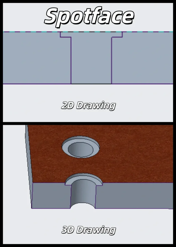
A spotface hole is an extremely shallow flat groove formed by spot face machining. Its core function is to flatten rough surfaces (castings, forgings) by removing unevenness or residues, providing a flat fitting surface for fasteners. It has a shallow depth (0.5~1.5mm, no strict tolerance, “spotface to clean up”) and does not need to accommodate fastener heads.
Spotface Hole in Engineering Drawings
Spotface dimensioning is simple: only spotfacing diameter and “spotface to clean up” are marked (no depth needed). For precision assembly, perpendicularity (≤0.05mm) is added. It reduces processing difficulty and cost, with optional fastener type indication for mass production.
Spotface Hole Symbol
The spotface symbol is abbreviated as “SF” internationally, or marked as “Spotface”. The format is “SF + spotfacing diameter + base hole parameters” (e.g., “SF φ40 φ12”), with no exclusive graphic symbol.
Standard Spotface Parameters Table
Below is the standard table for M3-M20 bolts, with depth as a reference (spotface until flat).
| Bolt Specification | Spotface Diameter (φ, mm) | Recommended Spotface Depth (mm) | Matching Cutter | Material Note |
| M3 | 6.0 | 0.5~1.0 | 6.0 Face Counterbore Cutter / Flat End Mill | Suitable for soft/hard materials |
| M4 | 7.0 | 0.5~1.0 | 7.0 Face Counterbore Cutter / Flat End Mill | Deepen to 1.0mm for cast iron |
| M6 | 10.0 | 0.8~1.2 | 10.0 Face Counterbore Cutter / Flat End Mill | Shallow for aluminum alloy |
| M8 | 13.0 | 1.0~1.5 | 13.0 Face Counterbore Cutter / φ13 Flat End Mill | Ensure fitting area for large heads |
| M10 | 16.0 | 1.0~1.5 | 16.0 Face Counterbore Cutter / φ16 Flat End Mill | Deepen for thick-walled workpieces |
| M12 | 18.0 | 1.0~1.5 | 18.0 Face Counterbore Cutter / φ18 Flat End Mill | For heavy-duty parts |
| M16 | 24.0 | 1.0~1.5 | 24.0 Face Counterbore Cutter / φ24 Flat End Mill | For flange holes |
| M20 | 30.0 | 1.0~1.5 | 30.0 Face Counterbore Cutter / φ30 Flat End Mill | For heavy-duty mounting holes |
Functional Comparison
Counterbores focus on hiding fastener heads, while spotfaces focus on flattening base surfaces. Their key functions are as follows:
Counterbore Functions
1. Hide fastener heads for aesthetics.
2. Prevent interference/scratching for moving parts.
3. Ensure sealing performance.
4. Adapt to precision assembly in space-constrained scenarios.
Spotface Hole Functions
1. Flatten rough surfaces for tight fitting.
2. Reduce processing costs with high efficiency.
3. Optimize force transmission to avoid stress concentration.
4. Adapt to rough base surface processing.
Machining Technology
The machining technologies of counterbore and spotface holes are determined by their structural and functional requirements, with differences mainly reflected in processing depth control, precision demands, and tooling strategy. The core principle is to meet functional needs while balancing efficiency and accuracy.
Counterbore machining technology follows the sequence of “drilling first, then counterboring.” After drilling the base hole, a counterbore cutter is used to machine the cylindrical recess. Cutting parameters must be adjusted according to material properties. For soft materials such as aluminum or copper alloys, spindle speeds are typically 2000–3000 r/min with feed rates of 0.1–0.2 mm/r. For harder materials like carbon steel or stainless steel, speeds are reduced to 800–1500 r/min with feed rates of 0.05–0.1 mm/r. Coaxiality between the counterbore and the base hole is critical to ensure proper fastener installation. A small chamfer, such as 0.5 mm × 45°, is often added at the bottom edge to reduce stress concentration.
Spotface hole machining technology (spot face machining) also follows the “drilling first, then spotfacing” sequence. After the base hole is completed, a spotface tool or flat end mill is used to remove a shallow layer of material and create a flat seating surface. For soft materials, typical speeds range from 2500–3500 r/min with feed rates of 0.1–0.2 mm/r, while harder or rough surfaces require lower speeds of 800–1500 r/min and feed rates of 0.05–0.1 mm/r. In difficult-to-access areas, back spotfacing can be performed using a dedicated back spotfacer. Unlike counterbores, spotfaces do not require strict depth control—the primary goal is to achieve sufficient flatness and surface cleanliness.
Application Scenarios
The application scenarios of counterbore and spotface holes strictly correspond to their functions. Accurate selection can be achieved by combining material characteristics, aesthetic requirements and assembly accuracy:
Counterbore application scenarios:
1. Parts with high decorative and aesthetic requirements, such as aluminum alloy chassis, 3C product casings, hardware accessories and equipment panels, to avoid head exposure affecting aesthetics;
2. Moving parts and anti-interference scenarios, such as mounting holes near guide rails, handles and transmission mechanisms, to prevent head scratching or hindering movement.
Spotface: Rough surfaces (castings/forgings), low-cost structural parts, large/thick workpieces, temporary positioning, heavy-duty bearing scenarios.
Spotface hole application scenarios:
1. Rough base surfaces such as castings, forgings and welded parts, such as machine tool bases, cast iron flanges and large welded structural parts, to remove surface unevenness and ensure fitting;
2. Structural parts with no aesthetic requirements and only need firm connection, such as steel structure supports, reducer casings and foundation bolt holes, taking into account both connection reliability and low cost;
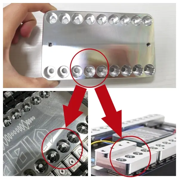
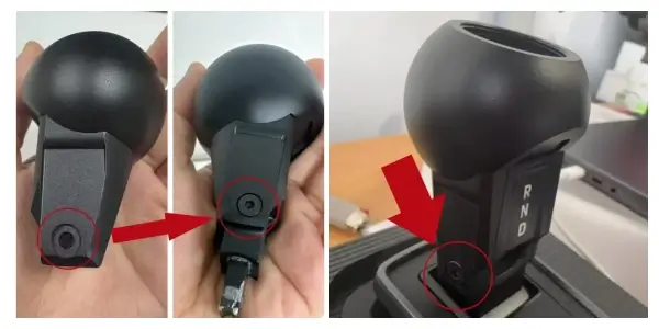
3. It’s also used in the automotive industry, for example, at the connection point of the car shift knob. We designed the product shown in the picture for our client, maintaining an aesthetically pleasing appearance while adding a secure mounting function.
Conclusion
The core difference between counterbore holes and spotface holes can be summarized as “counterbore is deep, hides bolt heads; spotface is shallow, flattens the base first”. Counterbore is characterized by a stepped structure and precise depth, which mainly serves the needs of hiding fastener heads and ensuring a flat surface, and is suitable for precision and appearance-oriented scenarios; spotface is characterized by an extremely shallow plane and flattening function, which adapts to the needs of rough base surfaces and low-cost connection, without the need to control depth.
In engineering practice, the selection should follow the principle of “function first, taking into account efficiency and cost”: if it is necessary to hide the fastener head and ensure a flat surface, select counterbore and strictly control the depth and coaxiality; if only the fitting surface needs to be flattened and there is no aesthetic requirement, select spotface and process according to “spotface to clean up”. At the same time, it is necessary to combine drawing dimensioning symbols (counterbore “⌴/CB”, spotface “SF/Spotface”), standard parameter tables and tool characteristics to ensure the consistency of processing and assembly. Mastering their differences can effectively avoid processing errors and improve workpiece quality and production efficiency.