Skip to content
 Almost all smooth motion systems depend on the small but mighty pinion gear. It plays a pivotal role in converting rotational motion into linear force. Such a transition enables everything to operate with precision and control.
What makes such a tiny mechanical thing so powerful? This article digs deep into the fundamental details of pinion gears. You’ll know its definition, working mechanisms, pros & cons, and applications to get its importance.
What Is a Pinion Gear?
It’s the smaller gear in any gear pair by default. Pinion gears mesh with a larger gear or a linear gear rack. The component plays a crucial role in transmitting torque and motion within mechanical systems.
Working Mechanism of Pinion Gears
The pinion rotates and moves the rack linearly in a rack-and-pinion system. This is how car steering converts the driver’s rotational input into lateral wheel movement.
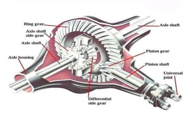
The pinion transfers torque to larger gears to adjust speed and force in gear trains. A pinion gear meshes with a ring gear to transmit power to the wheels in differentials.
The automotive pinion gear market is estimated to grow at a CAGR of 4.5% through 2030. Asia-Pacific leads in production, with China and India manufacturing millions of units annually.
Key Characteristics of Pinion Gears
a. Compact Design
Pinion gears are smaller than the other gears in the assembly. It allows space-efficient integration.
b. Tooth Profile
Most pinion gears feature involute tooth profiles. They ensure smooth engagement and minimal wear.
c. Tooth Count
Lower tooth counts increase torque with reduced speed. Common configurations range from 10 to 30 teeth, depending on the gear ratio.
d. Material Flexibility
High-strength alloys like hardened steel, stainless steel, and bronze are used for durability. Polymer-based pinions are employed in low-load applications.
e. Efficiency
Pinion gears in a rack-and-pinion can achieve 95% – 98% efficiency based on lubrication and alignment.
f. Load Capacity
Pinion gears are designed to withstand torques exceeding 500 Nm, especially in mining and heavy machinery.
Different Types of Pinion Gear
a. Spur Pinion Gears
Straight teeth come parallel to the gear axis. Spur ones are the simplest and most common type. They initiate high torque transmission without axial thrust.
Applications: Low-speed + high-load environments like conveyor systems, clocks, and basic gearboxes. Indian textile machinery uses spur pinions for synchronized roller movement.
b. Helical Pinion Gears
Helical pinions have angled teeth that engage gradually. They’re quieter and smoother than spur gears. Superior load-handling capacity comes from sufficient axial thrust.
Applications: Automotive transmissions, industrial compressors, and robotics. BMW and Toyota have helical pinions in electric steering systems to reduce noise (up to 30%).
c. Bevel Pinion Gears
Bevel pinions are conical gears to transmit motion between intersecting shafts. The compact design can transmit motion at 90° angles. They’re available in straight, spiral, and hypoid variants.
Applications: Differential systems in vehicles, aerospace actuators, and marine propulsion. Airbus A350 uses bevel pinions in its flap actuators for precise control of aerodynamic surfaces.
d. Rack-and-Pinion Gears
A rack-and-pinion system consists of a round pinion gear and a flat rack gear. The pinion rotates to move the rack linearly. It converts rotational motion to linear motion with a high efficiency (up to 98%).
Applications: Automotive steering, CNC machines, and railway locomotion. The Jungfrau Railway in Switzerland uses rack-and-pinion to climb gradients of up to 25%.
Benefits of Pinion Gears
a. High Mechanical Efficiency
Pinion gears, especially in rack-and-pinion systems, minimize energy loss during power transmission. They’re ideal for applications where energy conservation and responsiveness are required.
b. Compact and Lightweight Design
Small size and high torque-to-weight ratio make pinion gears perfect for space-constrained systems. Electric power steering (EPS) systems have compact helical pinion gears to reduce weight.
c. Precision and Responsiveness
Pinion gears provide precise control over motion, especially in linear applications. They enable accurate positioning of robotic arms and gantry systems for precise automation.
d. Versatility Across Gear Types
Pinion gears are available in spur, helical, bevel, and rack-and-pinion configurations. They can adapt to various torque, speed, and directional requirements. It renders them flexible across many industries.
e. Durability and Load Handling
Pinion gears can withstand 500+ Nm torques and operate continuously for over 100K hours. Such durability is essential in heavy-duty sectors like mining, marine propulsion, and wind turbines.
f. Cost-Effectiveness
Pinion gears are relatively simple to manufacture, especially spur types. Their low maintenance requirements and long service life reduce the total cost of ownership across industrial systems.
Common Pinion Gear Problems and Their Fixes
a. Misalignment
Improper alignment with the mating gear or rack causes uneven tooth wear, more friction, and reduced performance. You’ll observe vibration, noise, premature wear, and poor motion accuracy.
Introduce precision mounting systems and alignment tools during installation. Apply laser alignment techniques in industrial setups. Also, schedule regular inspection of gear mesh to adjust positioning.
b. Excessive Wear and Pitting
Continuous friction and load stress can cause surface degradation. It eventually leads to pitting and gear tooth erosion. Symptoms include rough operation, increased noise, and reduced gear life.
Choose surface-hardened materials like carburized steel. Apply synthetic lubricants featuring anti-wear additives. Additionally, implement scheduled lubrication cycles and oil analysis.
c. Backlash
It refers to the clearance between mating gear teeth. Backlash triggers inaccurate positioning and jerky motion. You’ll confront poor responsiveness in robotics or CNC systems.
Get anti-backlash gear designs with spring-loaded compensation. Enable tighter tolerance for precision applications by adjusting the gear spacing and preload settings.
d. Noise and Vibration
Abrupt tooth engagement can generate high noise and vibration levels, especially in spur pinion gears. You should notice audible gear whine, discomfort in automotive cabins, and reduced system efficiency.
Switch to helical pinion gears for smoother engagement. Install vibration-damping mounts and gear housings. Applying noise-reducing lubricants and coatings may lend a hand.
e. Lubrication Failure
Inadequate or contaminated lubrication leads to increased friction, overheating, and accelerated wear. Symptoms include gear scoring, heat spots, and reduced efficiency.
Implement automated lubrication systems. Find high-viscosity gear oils for heavy-duty applications. Regularly monitor oil quality and replace at scheduled intervals.
Alternatives to Pinion Gears
a. Worm Gear Systems
It consists of a screw-like worm that meshes with a toothed wheel. High torque transmission and speed reduction prevail throughout the system.
Applications: Elevators, conveyor systems, tuning instruments.
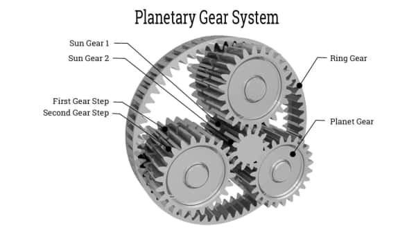
b. Planetary Gear Systems
A central sun gear is surrounded by planet gears that rotate within an outer ring gear. The design enables uniform/even load distribution.
Applications: Automatic transmissions, aerospace actuators, robotics.
c. Harmonic Drives
The components use a flexible spline and wave generator to achieve ultra-precise motion control with zero backlash.
Applications: Space robotics, surgical robots, semiconductor equipment.
d. Belt and Pulley Systems
A belt transmits motion between pulleys. It offers flexible and quiet power transmission.
Applications: HVAC systems, 3D printers, textile machinery
Conclusion
From steering to robots, pinion gears impart precision, power, and control. The versatility remains unmatched, proving that even the smallest components can’t be overlooked. Understanding pinion gears can unlock smarter design, improve efficiency, and solve real-world challenges.
Get Your Metal Gears for Industrial Uses at HRC
We’re a top-tier CNC manufacturing company that creates precise mechanical gears. HRC has been leading the industry for 17 years with commitment. Contact us to reach top industry experts for consultation.