Skip to content
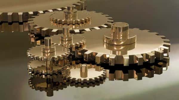
 Many components function simultaneously to run a machine with precision and power. And spur gear lies at the core of countless mechanical systems. It’s everywhere, from industrial machinery to everyday appliances.
Spur gears quietly but efficiently transfer motion + torque with remarkable efficiency. This guide breaks down every fundamental factor about spur gears. It delivers an actionable understanding of spur gears for your needs.
Spur Gear Overview
It’s a cylindrical gear with straight-cut teeth. The teeth are placed parallel to the axis of rotation. The gears mesh with other spur gears on parallel shafts.
Such collaboration enables the transfer of rotational motion and torque. A steady geometry makes them easy to manufacture and highly efficient for low to moderate speed applications.
It’s a power transmission component for torque delivery and speed regulation in mechanical systems. A spur gear is crucial where axial alignment is critical.
How Spur Gears Work?
Spur gears operate through direct tooth engagement. The meshing of two gears causes the teeth of one gear to push against the others’ teeth to rotate.
The contact occurs along the entire face width of the gear teeth. It results in a sudden load transfer, which can lead to noise at high speeds.
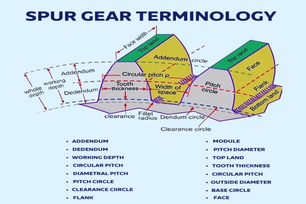
Key Elements of Spur Gear Mechanism
- Tooth Profile: Involute shape for smooth engagement and constant velocity ratio.
- Pitch Circle: Imaginary circle where gear teeth theoretically engage.
- Gear Ratio: Defined by the number of teeth on each gear for speed and torque output.
- Direction of Rotation: Opposite for meshing gears.
Characteristics of Spur Gears
a. Straight Teeth and Parallel Shaft Alignment
Spur gears have straight-cut teeth that are parallel to the gear’s axis. It allows smooth and consistent gear engagement. Parallel shaft operation also simplifies alignment and installation.
b. High Efficiency and Power Transmission
Spur gears can achieve 98% efficiency in power transmission due to low sliding friction. They transmit high torque at moderate speeds. That’s why it’s common in gearboxes and industrial drives.
c. Noise and Vibration at High Speeds
Sudden tooth engagement of spur gears can generate significant noise and vibration at high rotational speeds. For reference, the gears are best suited for applications below 3000 RPM.
d. Simple Manufacturing and Cost-Effectiveness
Spur gears are easier and cheaper to manufacture compared to alternative gears. Modern ones derive from steel, brass, plastic, or composite materials, depending on the application.
e. Constant Velocity Ratio
Spur gears maintain a constant velocity ratio. It’s a critical criterion for timing systems and synchronized motion. It makes the gears perfect for applications like clocks, printers, and conveyor systems.
f. Load Distribution and Stress Concentration
The entire face width of the gear teeth engages simultaneously. It leads to sudden load application and potential stress concentration. Wider teeth or hardened materials can mitigate wear + fatigue.
Different Types of Spur Gears
a. External Spur Gear
It’s the most common type where the teeth are cut on the outside of the gear cylinder. The gear meshes with other external gears to transmit motion between parallel shafts.
Applications: Automotive transmissions, conveyor systems, and industrial machinery. BMW gearboxes have external spur gears for torque transmission and speed regulation.
b. Internal Spur Gears
The teeth are cut on the inside surface of a hollow cylinder. They can mesh with external gears to enable compact gear arrangements.
Applications: Planetary gear systems, robotics, and compact mechanical drives. Japanese robotics firm FANUC deploys internal spur gears in servo motors to get high torque in a limited space.
c. Rack and Pinion
A linear gear (rack) meshes with a circular gear (pinion) to convert rotational motion into linear motion. It’s particularly suitable for steering systems and linear actuators.
Applications: Automotive steering, CNC machinery, and elevators. Rack-and-pinion systems have been the standard in North American vehicles for precise steering control.
d. Cluster Spur Gears
Multiple gears are mounted on a single shaft, mostly to change the gear ratios. Cluster gears enable multi-speed transmission systems.
Applications: Gearboxes, machine tools, and speed reducers. Such assemblies are integral to over 70% of industrial gearboxes across Asia.
e. Spur Gear with Hub
It includes a central hub for mounting on shafts. The gear provides better support and alignment.
Applications: Used in heavy-duty machinery and precision instruments. Hubbed spur gears in looms can maintain alignment under continuous load.
f. Spur Gear without Hub (Plain Bore)
There’s no central hub as the gear remains mounted directly onto shafts or bushings. The design is notably lightweight and cost-effective.
Applications: Small appliances, toys, and low-load systems. Chinese consumer electronics extensively rely on this gear for cost-effectiveness.
Benefits of Spur Gears
a. High Efficiency in Power Transmission
Spur gears can achieve impressive mechanical efficiency. Minimal sliding friction between the teeth directly contributes to such high ratings. It translates into reduced energy loss for power conservation.
b. Cost-Effective Manufacturing
The straight-cut teeth and cylindrical shape make spur gears simple to produce. High material flexibility also prevails. Spur gears can be of steel, brass, plastic, or even composites for cost optimization.
c. Easy Installation and Maintenance
Spur gears are straightforward to install and replace. Reduced downtime in industrial settings is almost guaranteed. A robust design and predictable wear pattern enable easy inspection and maintenance.
d. Precise and Predictable Motion
Spur gears maintain a fixed gear ratio. Such motion ensures synchronized motion between shafts. It leads to precision, which makes spur gears perfect for clocks, printers, and automation systems.
e. Minimal Axial Load
Spur gears generate no axial thrust. It simplifies the bearing selection with low lateral stress on shafts. Any compact systems where space and load distribution concerns can benefit from the feature.
Spur Gear Problems and Fixes
a. Tooth Wear and Pitting
Gear teeth can suffer from abrasive wear and pitting over time. Small craters form due to surface fatigue. It’s common in high-load or poorly lubricated systems.
Hardened steel or surface-treated materials with correct lubrication can resolve the issue. Consider scheduling routine inspections to detect early signs of wear.
b. Misalignment and Mounting Errors
Improper shaft alignment or loose mounting can cause uneven tooth contact. It leads to accelerated wear and noise.
Get precision alignment tools during installation. Implement rigid mounting systems with minimal play. Check for thermal expansion in high-temperature environments.
c. Backlash and Loss of Precision
Backlash indicates the gap between mating teeth. It can cause motion lag while reducing precision in control systems.
Use anti-backlash spur gears with spring-loaded mechanisms. Tighten the tolerances through software compensation in CNC and robotic systems.
d. Overheating and Lubrication Failure
High-speed or high-load operation can cause overheating. It degrades lubricants and accelerates wear.
Apply synthetic lubricants with high thermal stability. Consider installing cooling systems or heat sinks. Monitor temperature with infrared sensors or thermal cameras.
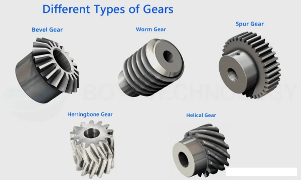
Spur Gear Alternatives
a. Helical Gears
Quiet and smooth operation due to angled teeth that engage gradually. They can handle higher loads and speeds with better efficiency in continuous operation.
b. Bevel Gears
Transmit motion between intersecting shafts, usually at 90° angles. They’re ideal for changing the direction of drive in compact spaces.
c. Worm Gears
High gear reduction occurs in a compact form, with self-locking capability. Lower mechanical efficiency prevails (50% – 90%) due to sliding contact, but it’s excellent for load holding.
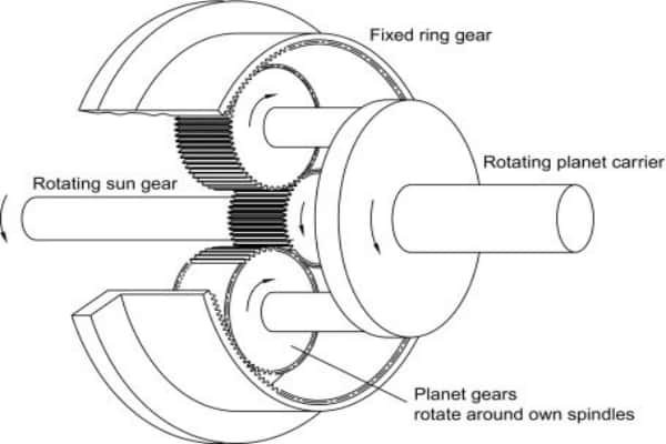
d. Planetary (Epicyclic) Gears
High torque density and compact design with multiple gear contacts. They offer high load capacity and balanced torque distribution.
e. Herringbone Gears
They effectively combine the features of helical gears without axial thrust. Such gears are complex and expensive, but ideal for high-load, high-speed systems.
Conclusion
Spur gears look simple in design. However, they’re anything but negligible parts. A spur gear delivers silent force to countless innovations. Mastering the fundamentals should let you make a proper choice.
Get Your Metal Gears for Industrial Uses at HRC
We’re a top-tier CNC manufacturing establishment that produces precise parts. HRC has been leading the industry for 17 years with satisfaction. Contact us to reach top industry experts for consultation.