 Skip to content

CNC Machining Case Studies
Real Parts. Real Challenges. Proven Results.
Explore selected CNC machining cases from HRCCNC, covering aluminum parts, steel components, precision-turned shafts, deep-hole machining, hard steel processing, and special anodized finishes. Each case highlights the material grade, machining method, tolerance requirement, surface roughness, surface treatment, core machining challenges, engineering solutions, and finished part inspection method.
- Material Grade
- Tolerance
- Surface Roughness
- Inspection
Selected CNC Machining Case Studies
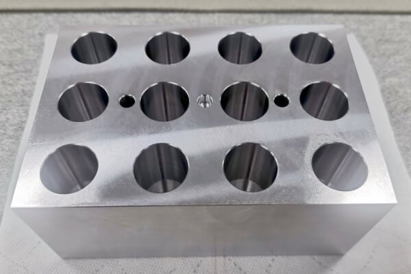
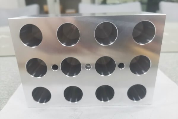
CNC Machined Aluminum Dry Bath Block with Precision Wells
A 6061-T6 aluminum dry bath block requiring deep-hole accuracy, fine internal surface finish, thin-wall stability, and clean burr control at intersecting holes.
This heating block was designed for laboratory equipment, where internal hole quality, dimensional accuracy, and clean finishing were critical to assembly and thermal performance.
Stable deep-hole straightness, controlled bore size, thin-wall deformation control, and burr-free cross-hole intersections after machining and cleaning.
6061-T6 Aluminum
5-axis CNC, BTA deep-hole drilling, boring, tapping, deburring
General ±0.03 mm; Ø6 deep hole +0.008 to +0.015 mm; position ±0.01 mm; straightness ≤0.05/100 mm
General faces Ra 1.6 µm; deep-hole inner wall Ra 0.4 µm
Natural hard anodizing, 12 µm film thickness
For precise and uniform heating of laboratory samples, test tubes, and vials.
- Very high length-to-diameter ratio deep holes were prone to vibration and poor straightness.
- Aluminum chip evacuation could scratch the inner hole wall.
- Thin-wall cavity structure was sensitive to clamping deformation.
- Cross holes created hidden burr risks.
- Used BTA gun drilling with 8 MPa high-pressure internal coolant and step drilling.
- Applied 24-hour stress relief after rough machining.
- Designed vacuum suction and multi-point support fixturing.
- Used floating spindle deburring and ultrasonic cleaning.
- Deep-hole roughness and straightness were treated as key quality controls.
- Thin-wall support strategy reduced clamping-related dimensional risk.
Inspection: CMM, pneumatic bore gauge, roughness tester, straightness plug gauge, and film thickness gauge.
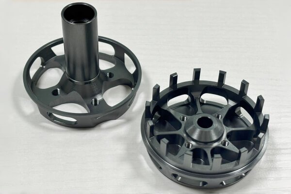
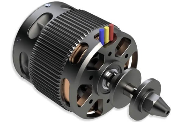
Drone Brushless Motor Housing
A 7075-T6 aerospace aluminum rotating component requiring bearing bore accuracy, concentricity, end-face runout control, heat dissipation slot stability and dynamic balance planning.
The housing supports a brushless motor assembly for aerial drones, where lightweight construction, precise mounting features, and dimensional accuracy are essential for stable assembly and reliable operation.
High concentricity, stable bearing fit, controlled slot indexing and consistent dynamic balance allowance after machining.
7075-T6 Aerospace Aluminum
3-axis CNC, turning-milling, precision boring, 5-axis heat dissipation slot milling
General ±0.02 mm; Ø22 bearing bore ±0.005 mm; concentricity 0.003 mm; runout ≤0.004 mm
Appearance surfaces Ra 0.8 µm; bearing bore Ra 0.2 µm mirror finish
Matte black hard anodizing, 15 µm film thickness
Aerospace & UAV Industry / Drone Propulsion Components
- Rotating parts required very high concentricity and runout accuracy.
- 7075 cutting stress could cause deformation and out-of-roundness.
- Thin-wall heat dissipation slots were prone to chatter marks.
- Dynamic balance allowance needed to remain consistent.
- Used turning-milling in one clamping to reduce datum transfer error.
- Separated roughing, semi-finishing, and finishing with low-temperature stress relief.
- Used micro carbide tools and side-support fixturing to reduce chatter.
- Reserved uniform finishing allowance for dynamic balance correction.
- One-clamping process planning reduced cumulative datum error.
- Bearing bore and runout were inspected as critical functional features.
Inspection: Roundness tester, dial indicator runout check, CMM, roughness tester and dynamic balancing tester.
Aluminum Dual-Color Anodizing Case
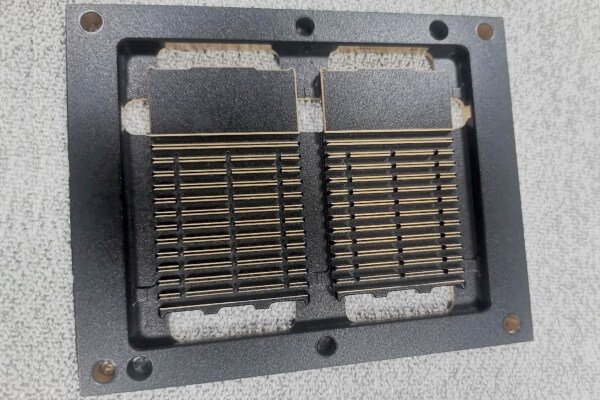
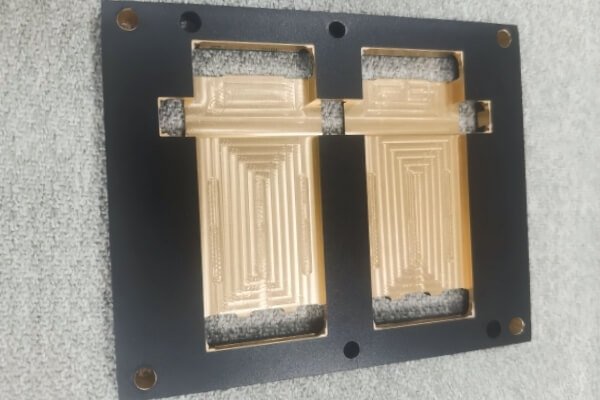
A special surface treatment case for aluminum parts requiring two anodized colors, clean color boundaries, dimensional control and stable cosmetic results.
This aluminum part required a black-and-gold cosmetic finish while maintaining machined dimensions and defined color boundaries.
Two anodizing colors, stable appearance, no boundary bleeding, controlled slot width, hole position and specified face flatness.
6061-T6 Aluminum
3-axis CNC machining
General ±0.02 mm; gold slot width 23.95 ±0.01 mm; Ø3.6 hole position 0.01 mm; face flatness 0.02 mm
Appearance surfaces Ra 1.6 µm; slot surface Ra 0.8 µm
Sandblasted black anodizing + gold anodizing
Cosmetic aluminum component / special surface finish demonstration
- Secondary anodizing and dyeing could create ash marks, streaks or uneven color.
- The first anodized color layer could be damaged or dissolved, exposing raw aluminum.
- Color bleeding could occur along the masking boundary.
- Locked anodizing temperature and strengthened bath agitation.
- Used anti-deformation hanging fixtures with auxiliary cathodes.
- Applied high-temperature sealing after the first anodizing step.
- Compressed masking edges or CNC-milled the base boundary to control color bleeding.
- Dual-color boundary control became the key quality feature.
- Surface treatment process was treated as part of manufacturing, not only post-processing.
Inspection: 2D optical measuring system, CMM, caliper and gauge block inspection.
Precision Drive Shaft in 45# Steel
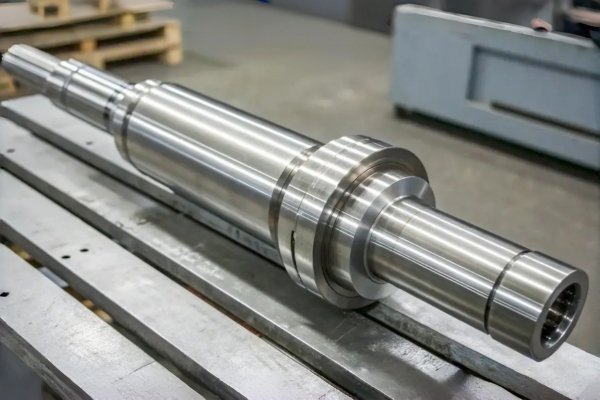
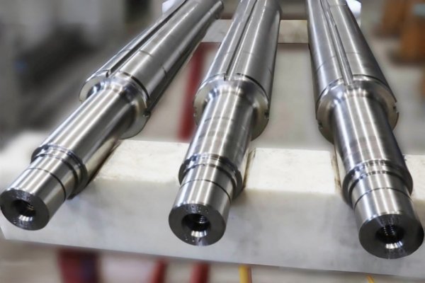
A CNC turning case for a quenched and tempered medium-carbon steel shaft requiring tight shaft diameter, step concentricity, thread accuracy and stable surface roughness.
This drive shaft was produced for mechanical transmission use, with multiple functional diameters, threads and bearing journal areas.
Stable deep-hole straightness, controlled bore size, thin-wall deformation control and burr-free cross-hole intersections after machining and cleaning.
45# Medium Carbon Steel, quenched and tempered to 220-250 HB
Slant-bed CNC turning, rough turning, finish turning, knurling, threading, cylindrical grinding
General ±0.02 mm; Ø12 / Ø16 shaft diameters ±0.004 mm; step concentricity ≤0.003 mm
General shaft sections Ra 1.6 µm; bearing journals Ra 0.4 µm
Quenching and tempering + black oxide; anti-rust oil on fitting surfaces
Industrial machinery, automation equipment, and power transmission systems.
- Slender shaft machining could cause tool push-off, bending, and poor concentricity.
- Quenched and tempered steel caused faster tool wear and unstable dimensions.
- Multiple steps and threads increased the risk of tool-change variation.
- Cutting heat could lead to deformation and dimensional springback.
- Used double-center support to reduce workpiece deflection.
- Selected CBN-coated turning tools with sufficient cooling and lubrication.
- Controlled finish turning depth within 0.1 mm.
- Allowed parts to cool to room temperature before final cutting and unloading.
- Support strategy helped control slender-part runout.
- In-process cooling reduced thermal size drift.
Inspection: micrometer, runout tester, thread go/no-go gauge, roughness tester, and height caliper.
Send your STEP, STP, PDF, DWG, or DXF drawing. HRCCNC can review the material grade, tolerance, surface roughness, surface treatment, machining risks, and inspection requirements before quotation.