Skip to content
 Smooth transmission of power in modern mechanical systems is impossible without helical gears. Unlike the straight-toothed spur gears, they operate with angled teeth that mesh gradually.
There are reasons why these gears are heavily preferred in high-speed + high-load applications across industries. However, what makes helical gears so special?
This article explores the mechanics, advantages, and real-world applications of helical gears in detail. You’ll understand every fundamental fact associated with the metal component.
What Is a Helical Gear?
It’s a cylindrical gear with an angle (helix) cut into the teeth to the axis of rotation. Helical gears engage gradually, initiating smoother and quieter operation.
The precision-engineered components transmit torque between parallel or non-parallel shafts. The angled teeth enable continuous contact during rotation.
Working Mechanism of Helical Gears
- Tooth Engagement: The angled teeth engage progressively rather than all at once. Such gradual meshing reduces shock loads and triggers quieter operation.
- Load Distribution: Because multiple teeth are in contact at any given time, the load is distributed across a larger surface area. It enhances durability and reduces wear.
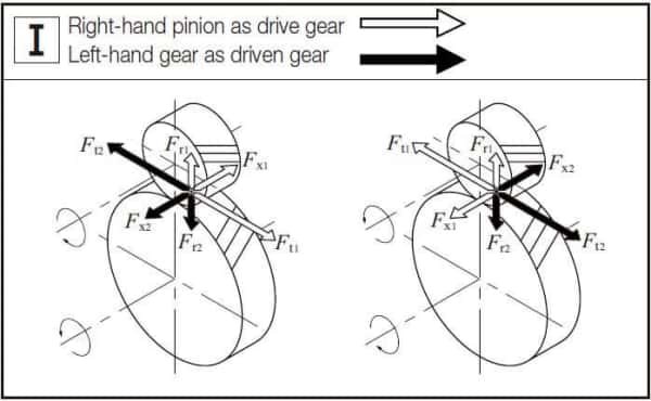
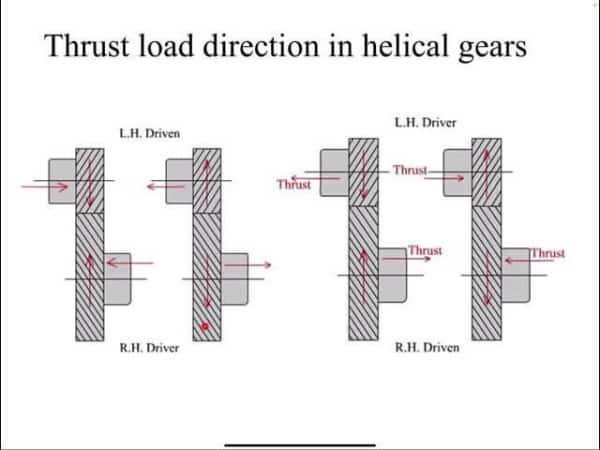
- Axial Thrust: The angled teeth generate a side force (axial thrust). It must be counteracted properly by thrust bearings in the gear assembly.
- Efficiency: Helical gears usually operate at 94% – 98% efficiency, depending on lubrication and alignment. The design supports higher torque transmission.
Characteristics of Helical Gears
a. Angled Teeth (Helix Angle)
The teeth, cut at an angle (15° to 30°) to the gear axis, form a helix. Such design specs allow gradual tooth engagement. It also reduces shock loads and noise.
b. Smooth and Quiet Operation
Multiple teeth remain in contact at once. Helical gears operate with up to 50% less noise than spur gears. They suit automotive transmissions, robotics, and office equipment like printers and copiers.
c. High Load Capacity
The distributed contact area enables helical gears to handle 30% – 50% more load. It’s common in heavy-duty machinery, such as conveyor systems, compressors, and wind turbines.
d. Axial Thrust Generation
The angled teeth produce a side force that requires thrust bearing counteraction. Dual helical (herringbone) gears oppose helix angles that cancel out axial thrust.
e. Versatile Shaft Alignment
Helical gears can transmit motion between parallel or non-parallel shafts. Such versatility supports complex gear arrangements in aerospace, industrial automation, and energy sectors.
Different Types of Helical Gears
a. Parallel Shaft Helical Gears
They transmit power between two parallel shafts using helically cut teeth.
Applications: Common in automotive transmissions, industrial gearboxes, and conveyor systems.
German CNC machines and Japanese robotics enable high precision + quiet operation.
b. Crossed Helical Gears
They transmit motion between non-parallel and non-intersecting shafts at right angles.
Applications: Found in instrumentation, small appliances, and low-power mechanical systems.
European medical devices + Asian textile machinery get compact and low-noise transfer.
c. Double Helical Gears
Two helical gears with opposing helix angles on the same gear body form a “V” shape.
Applications: Marine propulsion systems, heavy-duty compressors, and steel rolling mills.
Adopted in Chinese shipbuilding and Indian steel plants for high-load + continuous-duty.
d. Herringbone Gears
It’s a refined version of double helical gears with no gap between the opposing helices.
Applications: Found in high-torque industrial drives, hydroelectric turbines, and military machinery.
Brazilian hydroelectric plants and US defense equipment get rugged, high-load performance.
Benefits of Helical Gears
a. Higher Load Capacity
Multiple teeth are in contact at once. It enables more effective (uniform or even) distribution of the load.
b. Greater Durability and Longer Lifespan
Reduced wear prevails due to smoother engagement and better load distribution. You can even extend the gear life by 30% – 40% through lowered maintenance costs.
c. Versatile Shaft Configurations
They can transmit motion between parallel or non-parallel shafts. Aerospace auxiliary systems and industrial automation with space constraints demand flexible gear arrangements.
d. Reduced Wear and Tear
Gradual tooth engagement minimizes friction and mechanical stress. Lower vibration and heat buildup eventually lead to less frequent maintenance + improved safety in high-speed machinery.
e. Axial Thrust Management
Angled teeth produce side forces (axial thrust). Double helical and herringbone gears eliminate thrust. It seems perfect for marine propulsion systems and steel mills in India/Brazil.
Common Helical Gear Problems and How to Fix Them
a. Wear and Abrasion
Problem: Continuous sliding contact between angled teeth leads to material loss and profile distortion.
Apply high-quality lubricants to reduce friction. Select wear-resistant materials like case-hardened steel or nitrided alloys. Also, schedule routine inspections to detect early signs of wear.
b. Tooth Pitting and Fatigue
Problem: Repeated cyclic loading creates stress concentrations. It initiates surface pitting over time and eventual tooth failure.
Go for surface treatments like carburizing or shot peening to enhance fatigue resistance. Optimize gear design to reduce stress concentrations. Monitor load cycles to avoid overloading.
c. Bending Fatigue and Tooth Breakage
Problem: Excessive stress at the tooth root due to misalignment or overload results in a broken tooth.
Ensure precise gear alignment during installation. Deploy finite element analysis (FEA) in design to predict stress zones. Upgrade to double helical gears to balance forces.
d. Contact Fatigue (Spalling)
Problem: Microscopic cracks form due to repeated contact stress, leading to surface flaking.
Improve gear surface finish during manufacturing. Use EP (extreme pressure) lubricants to ease the contact. Implement condition monitoring systems to detect early signs.
e. Misalignment and Vibration
Problem: Poor installation or thermal expansion causes uneven tooth contact.
Choose precision mounting tools and thermal compensation techniques. Install vibration dampers or flexible couplings when possible.
f. Lubrication Failure
Problem: Inadequate or degraded lubricant leads to overheating. And an overheated surface triggers accelerated wear.
Consider implementing automated lubrication systems. Monitor lubricant quality and viscosity regularly.
Helical Gear Alternatives
a. Spur Gears
They’re gears with straight teeth aligned parallel to the shaft. You’ll enjoy a simple design, high efficiency (up to 98%), and lower cost.
Applications: Basic gearboxes, clocks, and manual tools.
b. Bevel Gears
Conical gears transmit motion between intersecting shafts, mostly at 90°. They’re perfect for changing the direction of power transmission.
Applications: Automotive differentials (Toyota Hilux, Ford Ranger) and marine steering.
c. Worm Gears
It’s a gear system where a screw-like worm meshes with a gear wheel. High reduction ratios come with self-locking capability to prevent back-driving.
Applications: Elevators, conveyor belts, and tuning instruments.
d. Planetary Gear Systems
A central sun gear remains surrounded by planet gears and an outer ring gear. High torque density + load sharing enables high-speed efficiency.
Applications: EV (Tesla Model 3, BYD EVs) and aerospace actuators.
Conclusion
Helical gears are more like the quiet force behind precision, power, and progress. The angled teeth silently drive innovation, efficiency, and reliability across industries. Leveraging helical gears unlocks better designs, steady machining, and more efficient systems.
Get Your Metal Gears for Industrial Uses at HRCCNC
Our top-quality CNC manufacturing company is ready to produce precise metal parts. HRCCNC has been leading the industry for 18 years with innovation. Contact us to reach top industry experts for consultation.