Skip to content


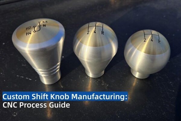
Buying a custom-machined shift knob isn’t complicated once you know how to send the right drawing and specifications. Each step of the manufacturing process has its blind spots, and most of them are easy to avoid once you understand the process. To help you do that, we at HRCCNC put together this step-by-step guide.
Custom shift knob manufacturing has three priorities: fit, finish, and verification. They run through all five major manufacturing steps we discuss below. We’ll also cover cost, lead time, and what to look for in a reliable manufacturer.
In this guide:
- Why use CNC machining for custom shift knobs
- Design and fitment requirements
- Step-by-step machining process
- Quality inspection and acceptance criteria
- Cost and lead time
- How to choose a custom shift knob manufacturer
Why Use CNC Machining for Custom Shift Knobs
Custom shift knob orders usually involve a high degree of customization, and quantities range from a single prototype to several thousand pieces. That’s a low-to-mid volume program. CNC machining is highly cost-effective for custom shift knob manufacturing at this scale, for two reasons:
- Low upfront tooling cost: CNC machining works with standard fixtures and soft jaws, not dedicated hard tooling. You can also scale on the same setup.
- Design flexibility: Revising the profile, logo, or grip texture means updating the CAD model and CNC program. There’s no major tooling rework.
If you have a fixed design and steady demand, die casting and injection molding can also be cost-effective options. Discuss it with your engineering team and your supplier. Both methods are initially expensive for low and mid-volume orders due to tooling cost. But once volumes go up, the unit price drops and the process can be scaled easily.
Table 1: CNC machining vs. die casting vs. injection molding for custom shift knobs
| Process | Tooling | Best fit | Trade-off |
| CNC machining | Fixtures only | Prototypes to mid volume | Higher unit cost at very high volume |
| Die casting + machining | Mold | Frozen designs, high volume | Threads and cosmetic faces need additional machining |
| Injection molding | Mold | Plastic knobs, high volume | Durable threads usually need a metal insert |
Design and Fitment Requirements Before You Machine
Get these details right before you send the drawing.
Thread Size, Depth, and Mounting Method
The first things to specify are the thread size (pitch and diameter) and the mounting method. You can refer to our shift knob thread size guide to shortlist your thread size and knob system.
But don’t rely on fitment charts completely, since aftermarket shifters and adapters can change the thread. Measure the shaft’s major (outside) diameter with a caliper and identify the pitch with a thread pitch gauge. Confirm both with your supplier before sending your RFQ.
Table 2: Common Shift Knob Thread Sizes
| Thread type | Common sizes | Typically found on |
| Metric (diameter × pitch, mm) | M10×1.25, M10×1.5, M12×1.25 | Many modern vehicles |
| Inch (diameter-threads per inch) | 3/8-24 | Older U.S. cars |
Before you order, confirm:
- Thread size: major diameter (caliper) and pitch (pitch gauge)
- Mounting method (a compatible jam nut helps lock the knob’s orientation)
- Shaft stick-out, so the bore is deep enough to seat the knob
- Need for a steel thread insert on aluminum knobs that get removed often
Mounting Height, Orientation, and Pattern Clocking
A taller knob gives the driver a longer throw with less effort. Whatever height you choose, make sure the knob clears the dashboard and center console in every gear.
If the knob has an engraved shift pattern, you also need to plan its alignment. A threaded knob stops wherever the thread ends, so the pattern can end up facing the wrong way. If your shifter accepts a compatible jam nut, you can turn the knob until the pattern faces the driver, then tighten the nut to hold it. If you’re adding a manual shift pattern for vehicles subject to the U.S. FMVSS 102, the pattern must be visible to the driver.
Reverse Lockout, Button Shifters, and Shift Boot Attachment
Check these three points that many buyers miss in their requirements:
- Lift-up reverse collars need sufficient space under the knob for the full lift. If the base is too low, the driver cannot engage reverse.
- Automatic shifters with a release button need a matching button, pushrod, and stroke length. They should be treated as an assembly, not a simple knob.
- Shift boots that attach directly to a threaded knob will twist as the knob is screwed on. To prevent this, use a free-spinning retainer ring or attach the boot at the jam nut.
Material, Weight, and Grip
Material choice decides most of the knob properties and limitations: the knob’s weight, finish options, and machining cost. The most common shift knob materials are:
- Aluminum 6061-T6 – lightweight, anodizes well, machines fast
- Stainless steel 304/316 – heavier and slower to machine.
- Acetal (POM) – lightweight, comfortable to touch.
See our shift knob materials guide for details.
On the drawing, state the exact grade and condition (e.g., 6061-T6) and a target weight in grams. For grip, specify the ball diameter, any knurling or grooves, and the surface finish. Bead-blasted or knurled surfaces grip better than polished ones.
Step-by-Step Process of Machining Custom Shift Knobs
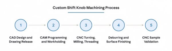
1. CAD Design and Drawing Release
Your 3D model defines the shape of the custom gear shift knob. Your 2D drawing defines what gets accepted. Set the thread axis as Datum A and control runout against it, because even small runout at the thread shows at the top of the lever. On the drawing, state:
- Full thread spec (e.g., M12×1.25-6H) and thread depth
- Cosmetic areas, target weight, and finish
Keep tight tolerances for critical features only (such as the thread, seating face, and button bore). HRCCNC can hold down to ±0.009 mm after drawing review, depending on material, geometry, feature, and process. Always state whether critical dimensions apply before or after finishing.
2. CAM Programming and Workholding
A round knob is hard to hold, so workholding is the main challenge in machining shift knobs. Ask your supplier how they handle it. A reliable approach is a two-step CNC turning process: first the base and thread, then the knob body on a threaded mandrel. Because the mandrel uses the same thread as the car, it usually keeps the body concentric to the thread. Runout still has to be measured and verified against the tolerance on your drawing. For milled features, ask for soft jaws to avoid clamp marks.
3. CNC Turning, Milling, and Threading
Each of these operations shapes a different part of your knob.
Turning creates the round knob body on a CNC lathe. When machining shift knobs, we always end the CNC turning process with a fine finishing pass. Otherwise, the rough feed marks become clearly visible once the knob is anodized.
CNC milling is performed to add flats, logos, finger grooves, and knurled grip areas. If your supplier uses CNC milling with live tooling on the lathe, these features are cut in the same setup. It keeps your cost down on small batches.
Threading creates the internal thread that holds the knob on the shaft. It’s either tapped or milled. For blind threads in aluminum, thread milling is the safer choice. There’s no risk of a broken tap, and the thread can be sized to allow for the anodized coating.
4. Deburring, Surface Finishing, and Customization
In this step, manufacturers usually make sure all burrs are removed before finishing, since anodizing won’t hide them. Bead blasting before anodizing is also a good approach to soften tool marks.
Then plan for coating buildup. Type II anodizing usually grows about two-thirds into the surface and one-third outward, so we mask the thread or machine it to final size.
You should also specify where the rack contact mark is allowed (inside the threaded bore is usually best). Ask for light-fast dyes since some organic dyes fade in sunlight. We also provide laser engraving services to add permanent graphics to your shift knob.
5. CNC Sample Validation
Before your sample ships, the manufacturer should check it against your drawing. At HRCCNC, we gauge the thread after anodizing, check runout on a threaded arbor, weigh the knob, and test-fit it on a gauge shaft that matches your thread and stick-out. We also check the finish and engraving against your artwork under consistent lighting.
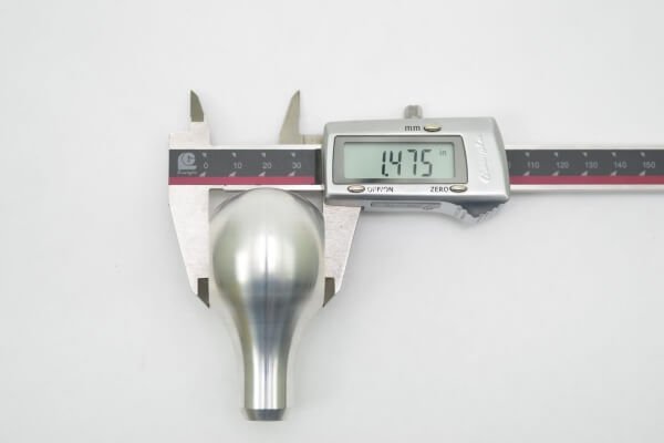
Once it passes, we deliver the sample. You must test it in the vehicle in every gear, with the boot and reverse lockout in place. Then sign off a golden sample. Every later batch of CNC-machined shift knobs is inspected against it.
Quality Inspection and Acceptance Criteria
In custom shift knob manufacturing, every inspection should link back to a drawing requirement or an application test. Without that link, acceptance becomes a matter of opinion.
Table 3: Shift Knob Inspection Methods and Acceptance Criteria
| Inspection item | Typical method | Acceptance basis |
| Internal thread | Go/no-go gauge after finishing | Thread class on drawing (e.g., 6H) |
| Bore depth, seating face | Depth gauge | Drawing and shaft stick-out |
| Profile and height | Height gauge or CMM | Drawing tolerances, console clearance |
| Knob body runout | Dial indicator on threaded arbor | GD&T callout to thread axis |
| Weight | Calibrated scale | Target weight and range on drawing |
| Anodize thickness | Eddy current per ASTM B244 | Finish specification |
| Color, texture, engraving | Visual check under defined lighting | Golden sample and artwork |
| Fit and function | Installation and shift test | Validation plan |
For repeat orders, use the same alloy lot and the same anodizing supplier whenever possible. This is where color differences between batches usually begin.
What Affects Custom Shift Knob Manufacturing Costs and Lead Time?
In CNC machining automotive parts, the number of setups is one of the major drivers of cost and lead time. Each additional fixture adds labor and setup time before the first approved part.
Table 4: Factors Affecting Custom Shift Knob Manufacturing Cost and Lead Time
| Cost Driver | Impact | Lead Time Impact |
| Setups and operations | Labor and fixturing for each setup | Programming and fixture build |
| Inserts, buttons, multi-piece parts | Extra parts and assembly | Component sourcing |
| Finish complexity | Polishing and multi-color anodizing need manual work | Often the longest step |
| Personalization | Unique engraving files need extra handling | Artwork approval rounds |
| Quantity | Setup cost is spread over more parts | Production scheduling |
| Inspection level | FAI and CMM reports add time | Report preparation |
Please confirm quotation turnaround, sample lead time, and whether finishing and inspection are included with HRCCNC before placing your order. Production lead time is confirmed after sample approval.
These timelines may change depending on finish, quantity, and workload. Ask your custom shift knob manufacturer to quote sample and production lead times separately.
How to Choose the Right Custom Shift Knob Manufacturer
A reliable supplier asks about your shaft, reverse lockout, and shift boot before discussing price. If the first questions are only about quantity and color, you may face problems at the sample stage.
Look for proven experience in CNC machining automotive parts, DFM feedback on thread design and coating allowance, in-house thread gauges, and documented certifications.
Quotation Checklist
- STEP model and 2D drawing with Datum A on the thread axis
- Thread specification, full thread depth, and measured shaft stick-out
- Mounting method: jam nut, set screw, insert, or adapter
- Reverse lockout type, button details, and boot attachment
- Material grade and condition (e.g., 6061-T6) and any required certification
- Target weight, finish, color reference, and cosmetic areas
- Engraving artwork, rack mark location, and pattern orientation
- Quantity per order and annual volume
- Inspection reports, sample quantity, and target date
Include these details in your RFQ to get a more accurate quote and lower the risk of fitment errors in your first sample. Every custom gear shift knob project at HRCCNC starts with this information.
FAQs
1. What are the main steps in custom shift knob manufacturing?
Custom shift knob manufacturing typically involves five steps: CAD design and drawing release, CAM programming and workholding, CNC turning and milling with threading, deburring and surface finishing, and sample validation before production approval.
2. How deep should the threaded bore in a custom shift knob be?
There is no universal bore depth. Provide the shaft stick-out and required thread engagement so the manufacturer can confirm that the knob seats securely without interfering with the shift boot or reverse-lockout collar.
3. Can anodizing affect the fit of a shift knob thread?
Yes. Anodizing changes aluminum dimensions and may tighten internal thread fit. Agree on coating allowances or thread masking before production, then check the finished thread with the specified go/no-go gauge. Technical reference
4. How can an engraved shift pattern be aligned after installation?
Where the shifter design allows it, a compatible jam nut can secure the knob at the desired angle. Check thread engagement, shift-boot clearance, and reverse-lockout operation after setting the orientation.
5. What should I check before approving a CNC-machined shift knob sample?
Check the finished thread, bore depth, body runout, weight, surface finish, and engraving against the drawing. Then test the sample in the vehicle through every gear, with the boot and reverse lockout installed.
6. What information is needed for a custom shift knob quotation?
Provide a STEP model and dimensioned drawing, thread specification, material grade, target weight, finish, engraving artwork, and order quantity. Include mounting details, inspection requirements, and the required delivery date.
Explore our custom shift knob capabilities, or send us your drawing for a DFM review that checks fitment before quoting.