Skip to content

Micro CNC machining isn’t just regular CNC work done smaller. Once a feature drops below about a millimeter, the physics of cutting changes: forces behave differently, heat behaves differently, even chip formation behaves differently. A mill that comfortably holds a few hundredths of a millimeter on a normal job runs into real limits fast at this scale. Micro machining exists specifically to work past those limits.
This guide walks through how the process actually works, what drives achievable tolerance, where things tend to go wrong, and what’s worth asking before a micro-scale drawing goes out for a quote.
What Is Micro CNC Machining?
Micro CNC machining is computer-controlled subtractive manufacturing aimed at parts or features smaller than roughly 1 mm. It runs on the same basic principle as any CNC process: a cutting tool follows a programmed path and removes material. What’s different is nearly everything surrounding that principle. Tooling, spindle speed, feed rate, workholding, coolant, inspection, all of it gets rebuilt around the scale involved.
| Factor | Standard CNC Machining | Micro CNC Machining |
| Typical tolerance band | Hundredths of a millimeter | Single-digit microns, under the right conditions |
| Tool diameter | Several mm and up | Often under 1 mm, sometimes under 0.1 mm |
| Spindle speed | Typically under 20,000 RPM | Commonly 20,000 to 60,000+ RPM |
| Coolant approach | Flood coolant | Mist, through-tool, or air/oil spray |
| Inspection method | Calipers, standard CMM | Optical comparators, high-resolution CMM, microscopy |
| Material removal rate | Cubic centimeters per minute | Cubic millimeters per minute |
Note: Figures above are general industry reference points, not a guarantee for any specific part. Actual achievable tolerance depends on material, geometry, and the equipment doing the work, which is exactly what the tolerance section below gets into.
How It Differs From Standard CNC Machining
The gap here isn’t really about size. It’s physics. At normal scale, a ten-micron variation is nothing, background noise nobody would notice. At micro scale, that same ten microns can eat up a meaningful share of the entire feature. The ratio of cutting force to material removed shifts hard once you’re under roughly 500 microns, tool runout that wouldn’t register on a standard job becomes a leading cause of error, and thermal expansion in the machine or the part itself can outweigh the tolerance band you’re aiming for. None of that gets solved by running a normal mill more carefully. It takes different equipment, built for a different job.
What Equipment Is Used for Micro CNC Machining?
Micro-capable equipment covers both milling and turning, and the two aren’t interchangeable. A micro CNC milling machine is engineered for rigidity and thermal stability first, with precision tooling as the second piece. Spindle speed is where this shows up first. These machines commonly run 20,000 to 50,000 RPM, sometimes past 60,000 for the smallest cutters. Why so fast? A tiny tool needs that rotation just to hold a workable cutting speed at the edge. Slow it down and the tool doesn’t really cut so much as rub.
Turning centers built for micro work follow the same logic from a different angle: rigid spindles, tight runout, and control systems that hold position at a resolution standard turning gear was never asked to manage. The frame matters just as much as the spindle on both machine types. A rigid, thermally stable structure is what keeps a feature from drifting as the machine heats up over a run. Most of this equipment also carries linear scales or encoders for feedback most CNC control loops don’t need at all.
The Micro CNC Machining Process
Micro Milling
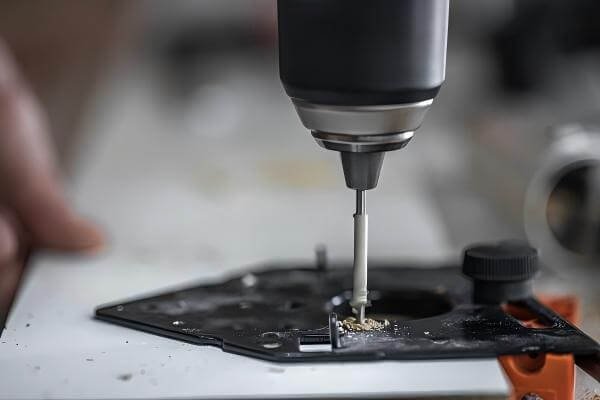
Micro milling uses cutters that are frequently under 1 mm in diameter, sometimes down to 0.05 or 0.1 mm on the smallest work. Feed rates stay conservative out of necessity, often somewhere around 0.002 to 0.005 mm per tooth, with depth of cut typically running 5 to 50 microns per pass and radial engagement kept to roughly 10 to 30 percent of tool diameter. There’s a reason the numbers are this cautious. A tool that would be perfectly fine on a standard job snaps almost instantly if it’s pushed the way a conventional end mill would be.
Micro Turning
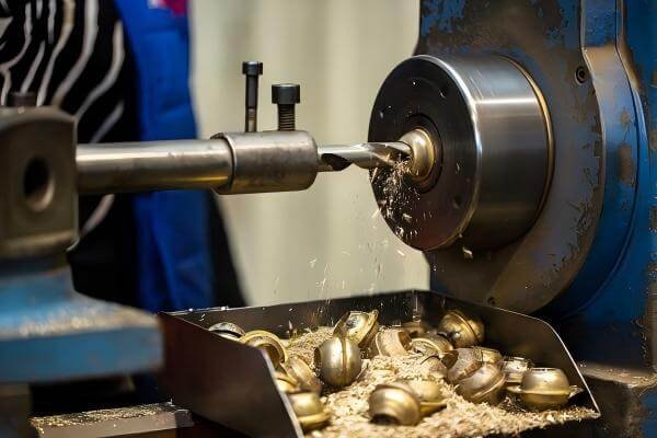
Micro turning applies the same caution on a lathe: small-diameter stock, light cuts, and real attention to how rigid the workpiece actually is, since a slender turned feature will deflect or chatter under forces a standard turning job would shrug off completely. Length-to-diameter ratio matters more here than in conventional turning too. A long, thin feature without enough support tends to taper slightly along its length as the tool passes, an error that’s irrelevant on a large part and very much not irrelevant on one that’s only a few millimeters across. This shows up constantly on pins, small shafts, and connector components.
Tooling: Working With Sub-Millimeter Cutters
Micro tooling needs specialized coatings and edge geometry just to hold up under normal use. A coating that works fine on a 6 mm tool behaves completely differently once you’re down at 0.3 mm. Tool runout below roughly 5 microns is generally what it takes to avoid early failure, and even a small misalignment in the holder can be the difference between a clean feature and a tool that snaps mid-cut.
Micro CNC Machining Tolerances: How Tight Is Tight?
Typical Achievable Tolerances
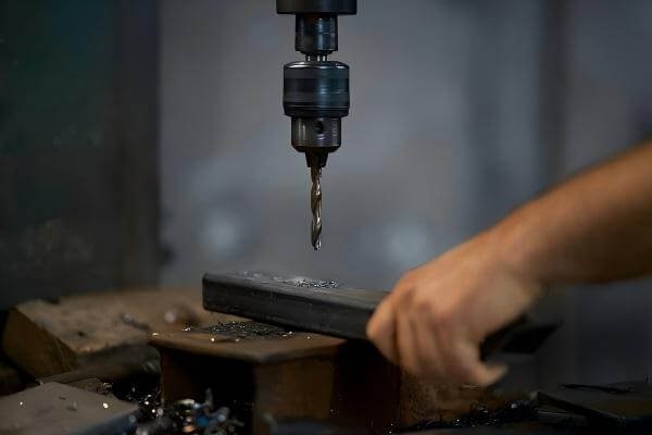
Typical tolerances in micro CNC machining vary depending on feature size, material, geometry, tooling, and machine capability. While micron-level tolerances may be achievable under controlled conditions, the realistic tolerance for a specific part should always be evaluated based on its drawing and critical features.
What Determines Achievable Tolerance
There’s no single number that applies across every micro part, and treating tolerance as a fixed spec you can quote in the abstract usually leads to disappointment somewhere down the line. Six factors decide what a shop can actually hold on a given feature, and changing any one of them shifts the realistic tolerance window.
Material
Some materials cut clean, others don’t. A soft, gummy material tends to deform rather than shear, which limits how tight a tolerance is realistic to hold. A free-machining alloy behaves far more predictably under the same cutting conditions.
Feature Size
Smaller features leave less room for error in absolute terms. A deflection or thermal shift that wouldn’t register at all on a larger feature can push a sub-millimeter feature outside tolerance entirely.
Geometry
Thin walls, deep pockets, and narrow slots all hold tolerance less predictably than a simple, well-supported shape, mostly because of how the tool has to approach and clear the cut.
Tooling
Tool diameter, runout, and condition all feed directly into what’s achievable. A micro tool that’s worn or slightly misaligned can shift a result well before it looks worn to the eye.
Machine Capability
The machine’s own rigidity, thermal stability, and positioning resolution set the ceiling everything else operates under. No amount of careful tooling or programming produces a result tighter than what the machine itself can hold.
Inspection Method
A stated tolerance is only as trustworthy as how it was measured. A feature checked with calipers hasn’t really been verified at micron scale at all, so the inspection method used directly affects how much confidence to place in the number on the report.
Tolerance Capability at HRCCNC
HRCCNC’s CNC equipment holds tolerances down to ±0.009 mm on suitable geometry, verified against the drawing through CMM-based inspection. Where a part sits within that capability depends on the same factors covered above, material, feature size, and geometry chief among them, so the accurate answer for any specific part comes from a DFM review against the actual drawing rather than a general number quoted upfront.
What Limits Precision at This Scale
Precision at micro scale runs into limits that don’t really show up in conventional work. A deep, narrow slot holds tolerance less predictably than a shallow, well-supported feature purely because of how the tool has to reach it. Aspect ratio, tool condition, and even the ambient temperature of the shop floor all play into the result, on top of the machine’s rated accuracy.
Specifying Tolerance Without Overpaying
Not every dimension on a micro part actually needs the tightest tolerance available. Calling out tight tolerance only where it genuinely matters, and leaving the rest at a more workable band, keeps a quote from being priced as though the whole part demanded the tightest number on the drawing.
Key Challenges in Micro CNC Machining
Tool Deflection and Breakage
Small-diameter tools flex and break more easily than standard tooling, and the margin for error narrows fast as diameter drops. Conservative feeds and shallow cuts manage that risk, but they come at a cost: micro machining runs slower per part than conventional work by nature. A component just a few millimeters across can still take hours on the machine.
Thermal Expansion and Vibration
Heat that wouldn’t register on a standard job can push a micro feature outside tolerance without much warning. Equipment built for this work resists thermal drift by design, and a lot of shops isolate micro machines on vibration-dampened platforms or run them in cleanroom-adjacent conditions, since even minor ambient vibration shows up directly in the finished part.
Chip Evacuation and Coolant Strategy
Flood coolant, the default on most conventional CNC work, doesn’t really work here. The sheer volume can physically displace a small part or a delicate feature. Micro machining tends to rely on mist cooling, through-tool coolant, or targeted air and oil sprays instead, chosen specifically to clear chips without disturbing the workpiece in the process.
Inspection and Metrology at Micron Scale
Verifying a feature that’s a fraction of a millimeter across takes more than calipers. Optical comparators, CMM probing with micron-level resolution, and sometimes microscopy are what confirm a micro part actually meets its drawing, rather than just trusting that the machine held tolerance because the program said it should.
Materials for Micro CNC Machining
Metals: Stainless Steel, Titanium, and Aluminum
Stainless steel and titanium turn up constantly in micro medical and aerospace parts, and there’s a real reason for that: both hold their dimensional stability well at small scale. The tradeoff is that neither machines as easily as aluminum.
Their thermal conductivity runs low, so heat concentrates right at the cutting edge instead of spreading out, and that’s about the worst thing that can happen to a micro-scale tool. Aluminum, by comparison, cuts more easily and tolerates a wider range of parameters without chipping tools or degrading finish. It’s a common choice when the application doesn’t specifically need the strength or biocompatibility that steel or titanium provide.
Engineering Plastics: PEEK, PTFE, and Others
PEEK and PTFE show up a lot in micro fluidic and medical components, but plastics bring their own kind of trouble. Heat sensitivity is the big one. Push too hard and the tool doesn’t cut the material so much as deform it locally, smearing instead of shearing.
Chips also tend to cling or build up static charge, which makes evacuation harder than it sounds at this size. A feed rate that cuts stainless cleanly can just as easily melt a plastic feature instead, so parameters really don’t carry over between material families without real rework.
Micro CNC Machining vs Other Micro-Manufacturing Processes
Micro CNC Machining vs Micro EDM
Micro EDM removes material through electrical discharge instead of cutting, which makes it well suited to extremely hard materials and geometry a cutting tool can’t physically reach, sharp internal corners being the clearest example.
Micro CNC machining tends to run faster and more cost-effectively on geometry a cutting tool can access directly, while EDM earns its place specifically where hardness or geometry rule cutting out: tight internal corners, hardened tool steel, or features with no straight-line tool access. Neither process is the default option. Which one fits comes down to the specific material and geometry in front of you.
When a CNC Micro Machine Beats Molding or Etching
A CNC micro machine wins over injection molding or chemical etching whenever volumes are low, the design is still likely to change, or the part needs a metal that molding simply can’t replicate. Molding and etching make more sense once volumes are high and a design is locked in, but a CNC micro machine doesn’t carry the tooling cost a mold requires, and a geometry change between iterations is just a program edit rather than a new tool built from scratch.
Applications and Industries That Rely on Micro CNC Machining
Medical Devices and Implantable Components
Surgical instrument tips, small implant components, and drug-delivery hardware all lean on the tolerance and material control micro CNC machining provides, frequently in titanium or stainless steel where dimensional consistency ties directly to patient safety.
Electronics and Connectors
Miniature connector pins, housings, and contacts increasingly need sub-millimeter features as devices keep shrinking, particularly across consumer electronics and telecom hardware.
Optics, Fluidics, and Sensors
Microfluidic channels, small optical mounts, and sensor housings depend on tight positional accuracy and a clean surface finish, since even a small dimensional error can change how fluid moves through a channel or how a sensor lines up with the components around it.
Watchmaking and Precision Instruments
Traditional precision fields like watchmaking remain a steady source of demand for micro-turned pins, gears, and small structural parts, where tolerance has been measured in microns for a very long time, well before “micro machining” existed as its own category.
Choosing a Micro CNC Machining Partner
Questions to Ask Before Sending a Drawing
Worth asking directly: what tolerances can the shop repeatedly hold on features similar to yours, not just what they say is theoretically possible on paper. What metrology do they actually use to verify a micro feature once it’s cut. And what’s their real experience with your specific material, since behavior at micro scale varies more by material than most buyers expect walking in.
Why Volume and Tolerance Together Drive Cost
Micro machining runs slower than conventional work by nature, a direct result of the conservative feeds and shallow cuts the process demands. That means cost scales with tolerance and volume together, not tolerance on its own. A tight tolerance on a short run prices out differently than the same tolerance spread across a large batch, which is exactly why an accurate number depends on the real drawing and quantity rather than a rough estimate.
FAQs
1. What is micro CNC machining?
Micro CNC machining is a subtractive manufacturing process used to produce very small parts or features, often below 1 mm. It uses specialized CNC equipment, small cutting tools, high spindle speeds, and precise inspection methods to maintain accuracy at the micro scale.
2. What tolerances can micro CNC machining achieve?
Achievable tolerances depend on the material, feature size, geometry, tooling, machine capability, and inspection method. Micron-level tolerances may be possible under controlled conditions, but each part should be evaluated based on its drawing and critical features.
3. What materials can be used for micro CNC machining?
Common materials include aluminum, stainless steel, titanium, PEEK, PTFE, and other engineering plastics. Material selection affects machinability, tool wear, thermal behavior, achievable tolerance, and the cutting parameters required.
4. What is the difference between micro CNC machining and micro EDM?
Micro CNC machining removes material with cutting tools, while micro EDM uses electrical discharge. CNC machining is well suited to accessible geometries, while micro EDM can be useful for hard conductive materials, sharp internal corners, and features that cutting tools cannot easily reach.
5. What parts are commonly made with micro CNC machining?
Micro CNC machining is used for miniature connector components, small shafts and pins, medical device components, microfluidic parts, sensor housings, optical mounts, and precision instrument components.
6. How do I choose a micro CNC machining supplier?
Look at the supplier’s ability to repeatedly hold the required tolerances, its experience with your material and geometry, and the inspection equipment used to verify critical features. Providing a detailed drawing allows the supplier to evaluate manufacturability and realistic tolerance requirements before quoting.
Get Your Micro CNC Machined Parts Quoted by HRCCNC
Our Approach to Micro and High-Precision CNC Machining
HRCCNC works across both CNC milling and CNC turning for parts that call for tight, micro-scale tolerances, with DFM review built into the quoting process so tolerance callouts and material choice get checked against what’s actually achievable before production starts. Production runs under ISO 9001:2015, with CMM-based inspection used to verify parts against the drawing.
Request a Quote in 3 Steps
1. Upload your drawing: STEP, IGS, or PDF, with critical tolerances and material clearly called out
2. Get a DFM review: confirming which features genuinely need micron-level tolerance and which don’t
3. Receive your quote: with lead time based on your actual geometry and volume