
Machining thin walls carries several manufacturing challenges. When the wall thickness of a part is small compared with its height and length, stiffness reduces significantly. Then, these parts start bending, vibrating, or moving out of tolerance even under moderate cutting forces.
With 18 years of CNC machining experience, we have developed specialized thin-wall machining strategies to control these risks. At the same time, we have also noticed common design errors that cause your thin-wall designs to fail at the DFM stage.
With this guide, we are sharing the industry best practices we recommend for thin-wall part design and machining. Refer to the minimum wall thickness charts, wall ratios, material options, and tooling strategies provided here to build a DFM-safe design that provides you with stable parts.
What Is A “Thin Wall” In CNC Machining?
As a general machining reference, walls below about 2.0 mm are often treated as thin-wall features. But in the manufacturing context, a “thin-wall” is not defined by its absolute thickness measurement. It is defined by the ratio between unsupported height and wall thickness, which gives a quantitative indicator of the wall’s lack of rigidity.
Height-To-Thickness Ratio = Unsupported Height / Wall Thickness
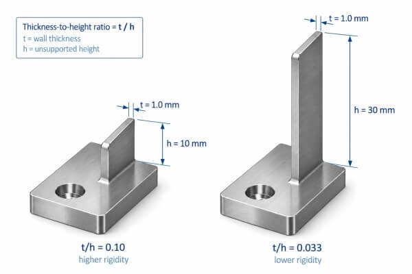
A higher height-to-thickness ratio means less stiffness or rigidity. If you take two aluminum walls with identical thicknesses, the taller wall will be more vulnerable to lateral cutting forces.
Minimum Wall Thickness For CNC Machining
Here are the common wall thickness limits for some of the popular thin-wall materials. Do not treat them as guaranteed production limits, and always ask your supplier for exact achievable limits.
Here, absolute minimum values represent aggressive machining limits under favorable machining conditions. It is always safer to stay above the recommended safe minimums for mass production.
Table 1: Minimum CNC Machining Wall Thickness Chart for Thin Walls
| Material | Aggressive Minimum* | Recommended Safe Minimum | CNC Thin-Wall Machining Concerns |
| Aluminum(6061-T6) | 0.5 mm | 0.8 mm | Deflection, chatter, spring-back |
| Stainless Steel(AISI 304) | 0.8 mm | 1.5 mm | High cutting forces, heat, taper |
| Brass(C360) | 0.5 mm | 0.8 mm | Burr formation, wall deflection, edge damage |
| Copper(C110) | 0.8 mm | 1.0 mm | Material smearing, heat buildup, deformation |
| Titanium(Ti-6Al-4V) | 1.0 mm | 2.0 mm | Heat buildup, tool wear, deformation |
| Engineering Plastics | 1.0 mm | 1.5 mm | Flexing, thermal distortion, clamping deformation |
Selecting a suitable minimum wall thickness is only the starting point. When you proceed to the design stage, the height-to-thickness ratio should always be treated as a key DFM guideline.
Height-To-Thickness Ratio Limits For Thin-Wall Machining
As a practical machining guideline:
- Ratios under 10:1 are usually comfortable for general machining. Walls remain rigid enough under normal cutting forces without being highly prone to deflection, vibration, or chatter.
- Ratios from 10:1 up to 15:1 are generally considered thin-wall features and require more advanced machining. They may need low-force cutting strategies, multi-pass machining, and custom fixturing to prevent the wall from bending.
- Extremely high ratios around 20:1 or above fall into more demanding CNC thin-wall machining conditions. These walls may require specialized techniques such as step-down milling routines and can cost significantly more.
However, these ratios are only based on general conventions, so do not treat them as exact hard limits. Factors such as material properties, part geometry, fixturing, and tooling also have a direct impact on CNC thin-wall manufacturing. For example, two geometrically identical walls made from 6061-T6 aluminum and AISI 304 stainless steel may behave differently during machining due to differences in stiffness, cutting forces, heat generation, and machinability.
Before finalizing the design, always discuss it with your supplier to decide the achievable wall thickness levels based on their machining capabilities.
Send us your thin-wall design for an HRC DFM review
Why Thin Wall Machining Is Challenging
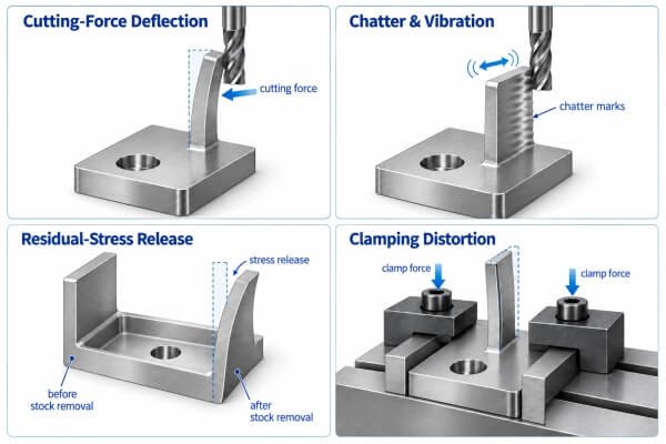
When the unsupported height increases, the wall starts to behave more like a flexible cantilever. Cutting forces acting near the top of the wall can push it away from the cutter. This creates several critical CNC thin-wall machining challenges.
Cutting-Force Deflection
When the milling cutter generates lateral forces, thin walls can physically move away from the cutter. After the tool passes, the wall springs partially back. This can lead to issues such as uneven wall thickness, taper, bowing, and perpendicularity errors. This also reduces the dimensional repeatability of the design.
Chatter and Vibration
When the stiffness is low, the wall becomes structurally unstable. When cutting, the wall begins to vibrate, producing an inconsistent cut. This leads to chatter marks, poor surface finish, reduced tool life, and dimensional variation.
Residual-Stress Release
Rolled, forged, and extruded stock usually contain residual stress. When you remove large amounts of material from one side, this stress balance can be disturbed. You might not see any issue while the part is still clamped, but it can distort after being removed from the fixture.
Clamping Distortion
Thin components can also be distorted before machining even starts. Excessive clamp pressure may elastically compress or bend the workpiece. The part tries to recover when released, and the final dimensions can shift out of initially planned tolerances.
How To Machine Thin Walls Successfully
Successful thin-wall machining requires controlling cutting forces, optimizing cutting parameters, maintaining part support, and minimizing clamping distortion. But simply reducing feed rates reduces efficiency and slows down production, which is not ideal for mass production. So, a reliable CNC thin-wall manufacturer should possess advanced machining capabilities to achieve efficient and repeatable production.
Keep the Walls Thicker for as Long as Possible
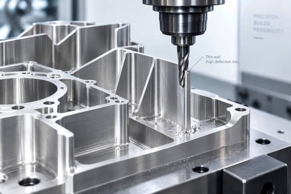
Manufacturers do not usually machine the wall to its final thickness too early. Leaving some stock material gives the part more rigidity during machining. The final wall thickness can then be reached with the final finishing passes.
Use Progressive Thin-Wall Milling
When machining thin-wall parts, cutting the full height at once is not recommended. We use a step-down strategy so that the unmachined lower section can support the cutting zone. Minimizing radial engagement is also a good machining practice for thin walls, as it limits lateral cutting forces and wall deflection.
Alternate Machining Sides
If the design allows access to both sides of the wall, alternating the cutting between both sides is a good practice. This helps balance cutting forces and reduces the tendency of the wall to bend in one direction.
Improve Fixturing and Wall Support
Flexible and custom fixtures can minimize excessive clamping forces. Additionally, using soft jaws, backing plates, sacrificial supports, custom nests, and vacuum fixtures where necessary can support thin walls across different geometries and thickness ranges. For complex thin-wall geometries, 5-axis machining can improve tool access and reduce repeated setups.
DFM Checklist for CNC Thin-Wall Machining
A thin-wall design should be reviewed beyond nominal wall thickness, especially focusing on the following areas:
Wall Thickness and Proportions
- Minimum wall thickness – Keep walls above the practical limit for the selected material.
- Height-to-thickness ratio – Higher ratios increase deflection and chatter risk.
- Unsupported length – Long thin sections can flex even at moderate heights.
- Ribs and transitions – Local reinforcement can improve rigidity without adding excessive weight.
Tool Access and Machining
- Internal radii – Larger radii allow more rigid cutters and reduce vibration.
- Tool reach – Deep walls may require long tool overhang, increasing deflection.
- Support stock – Temporary tabs, backing material, or sacrificial stock can maintain rigidity until finishing.
Tolerance and Fixturing
- Tolerance and surface finish – Avoid unnecessarily tight requirements on flexible sections.
- Clamping surfaces – Provide stable areas for fixturing without loading the thin wall directly.
Material and Production
- Material choice – Stiffness, residual stress, and machinability affect achievable wall thickness.
- Production volume – A prototype-friendly wall may still need design or fixturing changes for repeatable mass production.
FAQs
1. What is considered a thin wall in CNC machining?
As a general machining reference, walls below about 2.0 mm are often treated as thin-wall features. However, machining difficulty also depends on the wall’s unsupported height, material, geometry, tolerance, and fixturing.
2. What is the minimum wall thickness for CNC machining?
Minimum achievable wall thickness depends on the material and part geometry. For example, 6061-T6 aluminum may be machined down to around 0.5 mm under favorable conditions, while approximately 0.8 mm is a safer reference for repeatable production. Actual limits should always be confirmed through DFM review.
3. What height-to-thickness ratio is recommended for CNC thin walls?
As a practical guideline, ratios below 10:1 are generally easier to machine. Ratios between 10:1 and 15:1 require more careful machining strategies, while ratios around 20:1 or higher can significantly increase the risk of deflection, chatter, and dimensional variation.
4. How do you prevent thin walls from deforming during CNC machining?
Common strategies include leaving additional stock during roughing, using progressive step-down milling, minimizing radial engagement, alternating machining sides, and providing adequate wall support with appropriate fixturing.
5. Which materials are best for CNC thin wall machining?
Aluminum alloys such as 6061-T6 are commonly suitable for thin-wall machining because of their machinability. Stainless steel, titanium, copper, brass, and engineering plastics can also be machined into thin-wall parts, but their practical wall limits and machining challenges differ.
6. What information should I provide for a thin-wall machining quote?
Provide your 3D CAD model, material, required wall thickness, critical tolerances, surface finish requirements, and production quantity. A DFM review can then identify high-risk wall sections, fixturing constraints, and potential design changes before production.
Summary: From DFM To Reliable Thin-Wall Production
With today’s advanced CNC machining capabilities, very thin CNC walls are possible with carefully supported geometries and the right supplier. But to safely achieve desired thin-wall limits, your design should follow practical DFM guidelines to minimize the loss of stiffness, deformation, chatter, and residual stresses. For a smooth process of CNC thin-wall machining, you should consider these factors during design rather than trying to correct an unstable geometry after machining begins.
Upload your 3D model here and get practical insights into risky wall sections, fixturing constraints, and design adjustments before production.