Aluminum is one of the most popular materials for CNC machining parts in several industries, such as automotive, aerospace, electronics, industrial, consumer products, etc. This is largely due to aluminum’s low weight, excellent machinability, and corrosion resistance. However, because of its softness compared to many other metals, working with CNC-machined aluminum parts may come with a few problems.
Without proper process control, CNC-machined aluminum parts can develop thin-wall deformation, burrs, damaged threads, poor surface finish, and other defects. Eventually, they manufacture faulty aluminum CNC parts that you cannot assemble into the final device. These ruined parts result in high scrap rates and unexpected costs. Moreover, the manufacturer needs to produce more batches of the parts to replace the faulty parts. Longer lead times lead to more delays in your final project.
However, these problems are preventable in both the machining and surface finishing stages by an experienced manufacturer like HRCCNC. In this article, I’ll discuss some common problems our engineering team at HRCCNC faces. I’ll also include how our team prevents them to make sure we supply aluminum parts with accurate dimensions and surface finish.
Common CNC Aluminum Machining Defects and Solutions
Problem 1: Thin-wall Deformation
A very common problem while CNC machining aluminum parts is thin-wall deformation, which occurs when the aluminum wall becomes extremely thin. You can identify it by focusing on the slight bow, twist, or curves on the thin wall. These deformations may occur during machining or unclamping.
Thin-wall deformation occurs for several reasons. When clamps hold the aluminum block too tightly during machining, the clamping force may bend the thin wall once unclamped or when the pressure is released. Excessive cutting force may push the aluminum thin wall too hard and bend the edges during cutting. If a thin-walled aluminum part becomes too hot during machining, thermal expansion and subsequent cooling can cause distortion.
This deformation may also occur due to residual stress in the aluminum block. When the material is machined into a thin-walled part, residual stress may be released. This causes the wall to twist or bow out of the accurate shape. Another common cause of thin-wall deformation is uneven stock removal, which means cutting metal from both sides of the thin aluminum wall unevenly. Such CNC-machined aluminum parts with deformed thin walls end up as scrap and cause your project to be delayed.
Solution:
HRCCNC team utilizes certain techniques acquired from experience and ensures the thin wall does not bend. To control excessive clamp force, we use special flexible holders and vacuum suction plates instead of extremely tight clamps. This distributes support to the aluminum part without causing any bending.
To balance roughing and material removal, we use light cuts and optimized feeds and speeds to reduce cutting forces on thin walls. Material is removed gradually and evenly whenever possible to minimize stress release and deformation.
Lastly, the team inspects the thin-wall accuracy and post-unclamping bow or twist using a Coordinate Measuring Machine (CMM) and 3D optical surface scanners.
Problem 2: Burrs
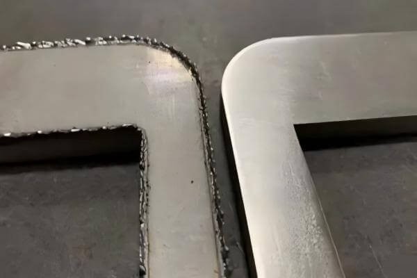
These look like sharp lips, feathered and rolled material at the exits of holes, edges, and cutter exit spots on CNC-machined aluminum parts.
Burrs can cause serious consequences; sharp edges on an aluminum part can scratch or cut through workers’ gloves, causing injury. Besides, when two parts are supposed to fit together in the final assembly in a device, burrs can hamper that due to a lack of required smoothness. Moreover, when a part with burrs is assembled into a device, the extra material may break off from the part inside the final device. This may scratch up other parts and reduce the overall performance of your device.
There are several reasons for the formation of burrs. One of the most common causes is the use of worn or damaged cutting edges. Such dull edges push the material and drag it to the cutter exit locations, instead of cutting the aluminum block cleanly. Also, aluminum is inherently softer than most other materials, which is also responsible for burrs instead of clean cuts.
It can also form because of weak support and a poor cutter exit strategy. If the cutting machine is too rushed or turns in the wrong direction, it can drag the metal off the existing points. Light rubbing or an unsuitable chip load can cause burr formation as well.
Solution:
HRCCNC is equipped with sharp aluminum cutting tools to prevent burrs and try to make every edge clean. We ensure a controlled cutter exit with a smooth or gentle turn to prevent dragging or stretching off any material from the edge surface.
Besides, in case of burrs, we execute a controlled deburring operation with small rounding tools to remove sharp edges and gently polish the affected areas. We also find a suitable chip load to avoid light rubbing causing any burrs. The chip or piece of aluminum to be removed from the workpiece is made thick enough to result in a clean cut instead of rubbing. To verify edge quality, we use magnification or optical comparators, complemented by a tactile pin gauge.
Problem 3: Built-up Edge and Poor Surface Finish
The effect of build-up edges (BUE) is very visible on the CNC-machined aluminum part. They can be identified at locations of torn finish, smeared surface, and unstable dimensions.
A build-up cutting edge can result in poor surface finish. A cutting edge with aluminum build-up causes an ‘As-machined’ surface finish with visible machining marks, stains, scratches, and texture differences. It also causes inconsistent parts production in the same batch. This requires thorough inspection to distinguish parts with accurate dimensions from those with unstable dimensions.
Aluminum CNC parts machined with a build-up edge require rework, causing you unexpected costs. Or they result in an increased scrap rate. When the thickness of the chip is insufficient, the cutting edge can rub the cutting surface, causing heat in the absence of coolant. Poor lubrication can also cause friction and heat. Aluminum, being a softer metal with a lower melting point than many other metals, sticks to the cutter edge.
Once a small amount of aluminum sticks to the cutter, more aluminum keeps building up on it due to aluminum adhesion. Such build-up on the cutting tool directly affects the cutting surface. Machining aluminum with built-up edge or unsuitable tool geometry can result in dimensional inconsistencies.
Solution:
To prevent build-up edges on the cutting tool, our team uses high-pressure coolant blasted at the tip of the cutter. This prevents soft aluminum from sticking to it. Controlling chip dimensions and cutting at high speed helps with a cleaner cut. Besides, we use sharp cutting tools with polished cutting edges designed for aluminum machining, which helps reduce material adhesion and built-up edge formation. To ensure the required Ra value, we measure the roughness of the machined face using a calibrated contact profilometer.
Problem 4: Chatter Marks
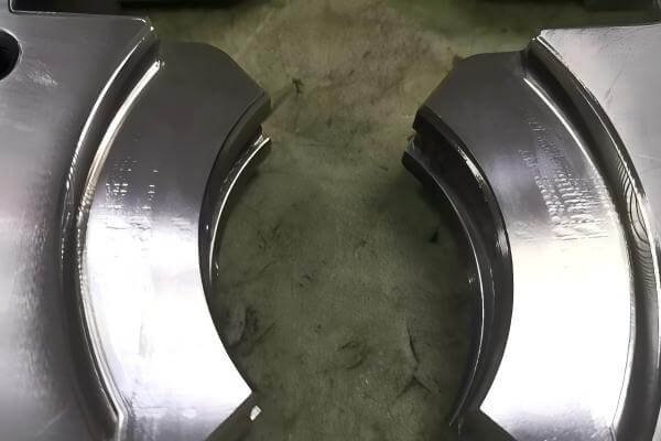
Chatter marks look like repeating fine waves, or vibration marks on a machined surface. Several aspects can cause these marks, such as low rigidity, long tool, thin wall, unstable engagement, resonant speed range, etc.
If the machining tool does not have a strong setup or is not clamped down rigidly, a loosely held tool may wobble and create wavy chatter marks on the surface. A tool with excessive overhang may also cause vibration during machining, resulting in chatter marks. Besides, when cutting tools are engaged with the aluminum part unstably instead of a smooth and steady cut, the machine may shake, causing a wavy pattern to form.
The consequences of such chatter marks are unsuitable aluminum CNC-machined parts. These parts may not fit your final device due to their unplanned ripples on the surface. This may require rework, causing you unexpected costs and more lead time.
Solution:
To prevent chatter marks on your custom CNC aluminum parts, the engineering team at HRCCNC uses an ultra-rigid setup for both the aluminum workpiece and cutting tool. We use a suitable cutting tool length to prevent any vibration caused by tool overhang. If chatter occurs within a resonant speed range, our team adjusts the spindle speed to move the cutting process away from unstable conditions and reduce vibration. Lastly, we inspect data on surface wave frequency and peak-to-valley chatter depth by optical profile projectors and surface roughness testers.
Problem 5: Dimensional or Tolerance Problems
Sometimes CNC machining aluminum parts comes across a problem that may not be as visible as many other problems. During a batch, after a warm-up or tool changes, the dimension or tolerance drifts from the specification. Aluminum parts machined early usually may not show any dimensional alteration. However, later parts may move out of specification.
Some of the main causes of this problem are tool wear or build-up edge on the cutter, fixture contamination, thermal change, offset variation, etc. When a machine operates for a long time, it may get heated, expanding both the contact surface of the aluminum workpiece and the cutting tool. This may make the later manufactured aluminum parts slightly out of the specified dimensional range.
Besides, tool wear due to a long operational period may result in less metal removal than initially programmed. In contrast, build-up edges on the cutter due to long operational time may cause more metal removal from the workpiece. In both cases, the dimension or tolerance drifts from the intended value. Another common cause is fixtures being contaminated with chips or small particles of metal, making the workpiece sit slightly tilted. This may cause variation in dimensions of different parts manufactured over time.
Solution:
HRCCNC tries to prevent dimensional or tolerance drift on aluminum parts by operating the machining equipment in a room with a controlled temperature. We maintain a steady cool temperature to avoid thermal expansion of the metal.
Our team uses air blasts and automatic cleaning methods to keep fixtures clean and prevent chips or debris from becoming trapped between the workpiece and fixture. Moreover, the cutting tool is measured and verified before machining new parts. To verify critical dimensions and tolerance drifts across batch runs, we use CMM automated routine checks, height gauge, and calibrated digital micrometers.
Problem 6: Damaged Threads
You can identify a damaged thread by spotting any stripped or cross-threaded internal ridges of the screw hole. Bolts can no longer grip a stripped thread as the spiral grooves get flattened. You can also find damaged threads when ridges exist inside the screw hole, but the bolt cannot tighten down; it keeps on spinning. Besides, in some cases of thread damage, the bolt face cross-threads, resulting in alignment with the wrong thread at a skewed angle.
One possible cause of damaged threads is using improper tapping parameters, such as excessive speed or inadequate lubrication. This can tear up the inside, and instead of uniform sharp grooves, the screw hole gets crushed or smoothed inside.
Due to its softness, the aluminum forming the ridges may stick to the thread-forming tool and tear the spiral wall inside when the tool is unscrewed. Besides, inserting a bolt at the wrong angle creates a new path at the spot of the original threads. Consequently, the parts cannot be assembled with any bolt. Sometimes, a screw can get stuck inside, making it unusable and increasing your scrap rates.
Solution:
We use synchronized, gentle, and computer-controlled rotation speed and downward pressure on the tool used for thread formation. Besides, when appropriate, we use thread-forming taps that create internal threads by plastically displacing the aluminum rather than cutting away material and producing chips. To inspect internal thread accuracy, we use go/no-go thread plug gauges and optical bore inspection scopes.
Problem 7: Anodizing Color Variation and Cosmetic Defects
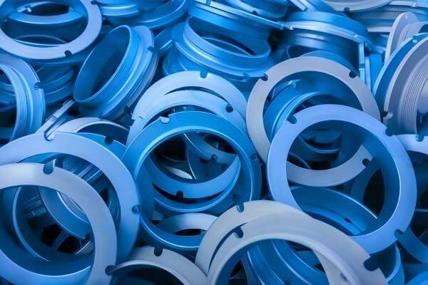
CNC machining aluminum parts often faces a problem involving altered or uneven anodizing appearance. It looks like aluminum parts have slightly different colors on different pieces during the surface finishing. Besides, sometimes the color may have uneven spots.
Causes of color variation and cosmetic defects usually involve material, surface, and process conditions. Variations in these parameters change the color to different tones across several aluminum parts. One of the common causes of mismatched color is using different aluminum alloys for producing the same parts.
Different alloys have different dye absorption capabilities. Patchy spots can occur due to remnants of cutting oil, grease, and fingerprints on the surface prior to a dye bath. Inconsistent temperature, electricity, or duration may also cause anodizing color variation.
Solution:
HRCCNC controls anodizing variables such as alloy consistency, surface preparation, and process parameters. We try to prevent anodizing color variation on your aluminum parts by using a specific alloy for production across all batches. Before anodizing, we suggest a pre-surface finish like gentle bead blasting or polishing to smooth the surface for anodizing.
Besides, before applying any dye to the anodized aluminum parts, we perform a deep cleaning procedure to reduce the possibility of uneven patches. Along with visual inspection in standardized daylight illumination booths (D65), we inspect anodizing color consistency and uniformity with spectrophotometers.
FAQs About CNC Machining Aluminum Parts
- What are the most common problems with CNC machining aluminum parts?
Common problems include thin-wall deformation, burrs, built-up edge, poor surface finish, chatter marks, dimensional or tolerance issues, damaged threads, and anodizing color variation. Proper tooling, machining parameters, fixturing, and inspection can help reduce these defects.
- Why do thin aluminum parts deform during CNC machining?
Thin aluminum parts can deform because of excessive clamping or cutting forces, heat buildup, residual stress, and uneven material removal. Using proper workholding, light cuts, optimized feeds and speeds, and balanced material removal can help minimize deformation.
- How can burrs be reduced when CNC machining aluminum?
Burrs can be reduced by using sharp cutting tools, maintaining an appropriate chip load, providing sufficient workpiece support, and controlling the toolpath and cutter exit. Controlled deburring can remove any remaining sharp edges after machining.
- How can tight tolerances be maintained on CNC machined aluminum parts?
Maintaining tight tolerances requires controlling tool wear, temperature changes, fixture cleanliness, cutting tool conditions, and machining parameters. Critical dimensions should also be verified with suitable inspection equipment such as CMMs and calibrated measuring tools.
- What causes poor surface finish when machining aluminum?
Poor surface finish can result from built-up edge, inadequate lubrication, improper chip load, worn tools, or chatter. Sharp tools designed for aluminum, proper coolant delivery, optimized cutting parameters, and a rigid machining setup can improve surface quality.
- Why can anodized aluminum parts have color variations?
Anodizing color can vary because of differences in aluminum alloy, surface preparation, cleaning, dye absorption, temperature, electrical conditions, and processing time. Consistent materials and tightly controlled anodizing parameters help improve color uniformity.
Partner With HRCCNC to Overcome CNC Aluminum Parts Problems
HRCCNC is equipped with CMM and optical metrology, In-process tool monitoring, and surface and thread monitoring to prevent several machining and finishing problems. We are an end-to-end manufacturer who can handle every step to supply high-quality aluminum parts. These include dimensional accuracy, smooth surfaces, and clean cuts. From aluminum alloy suggestions based on application to reliable worldwide shipping, we can help you with every step.
Besides, for free technical advice, you can contact us with your drawings for DFM feedback. Before sending drawings, ensure they cover crucial specifications like aluminum alloy, tolerances, critical dimensions, surface finish, quantity, and application. We can analyze your part specifications and warn you about possible common problems with your custom CNC aluminum parts.