Skip to content
 CNC machine programming follows a structured workflow that transforms a CAD design into machine-readable instructions. The process typically includes part analysis, CAD/CAM preparation, toolpath generation, code verification, machine setup, test cutting, and final inspection. This workflow guides the machine through precise machining operations while improving accuracy, consistency, and production efficiency.
Each step contributes to programming accuracy, toolpath reliability, machining efficiency, and finished part quality. The programmer must verify geometry, choose appropriate machining strategies, generate compatible G-code, and validate the program through simulation and test cuts before production begins. After machining, part inspection provides feedback for refining toolpaths, offsets, and cutting parameters. Following this structured CNC machine programming workflow helps reduce setup errors, prevent tool collisions, improve dimensional accuracy, and produce consistent machining results across production runs.
The CNC machine programming process typically includes the following steps:
- Step 1: Analyze the Part Drawing and Define Machining Requirements: Review drawings and tolerances, plan the machining sequence, and select workholding and tools to establish an effective CNC programming approach.
- Step 2: Build or Import a CAD Model: Create or import a CAD model, verify all geometry and dimensions, and prepare a CAM-compatible file that accurately represents the finished part.
- Step 3: Select CAM Software and Generate Toolpaths: Import the CAD model into the CAM software, define machining operations, set cutting parameters, and generate toolpaths to guide the CNC machine through each operation.
- Step 4: Choose Cutting Tools and Set Feed Rates and Speeds: Select cutting tools that match the material and geometry, then configure spindle speeds and feed rates to achieve efficient and accurate machining.
- Step 5: Write or generate the CNC Machine Code: Convert toolpaths into machine-readable CNC code and verify that all commands, tool movements, and machining operations are programmed correctly.
- Step 6: Simulate the Program and Check for Collisions or Errors: Run software simulations and machine dry runs to detect collisions, toolpath errors, and programming issues before machining begins.
- Step 7: Configure Work Offsets and the Coordinate System: Establish part zero, assign work offsets, and verify coordinate positions to ensure the CNC machine follows the programmed toolpaths accurately.
- Step 8: Load the Program and Run a Test Cut: Load the CNC program into the controller, perform an air cut, and execute a controlled test cut to validate machining performance and safety.
- Step 9: Inspect the Machined Part and Refine the Program: Measure the finished part, compare results against specifications, and refine the CNC program or machining parameters to improve future production accuracy.
Step 1: Analyze the Part Drawing and Define Machining Requirements
Start by reviewing the part drawing to understand all dimensions, tolerances, surface finish requirements, holes, slots, pockets, threads, and other critical features. Confirm that the part geometry fits within the CNC machine’s travel limits and identify areas that require precise machining. To execute this properly, scan all geometric dimensions, note tight tolerances such as ±0.01 mm that may require dedicated finishing passes, and check the material callout, such as 6061-T6 aluminum or 304 stainless steel, since material properties directly influence tooling, cutting parameters, and machining strategy.
Define the machining sequence by arranging operations such as facing, roughing, drilling, and finishing in a logical order. Select a suitable workholding method, such as a vise, chuck, or fixture, and ensure the material is securely clamped without obstructing tool movement. Then choose cutting tools that match the material and feature requirements. This analysis improves machining accuracy, reduces setup risk, and helps produce a high-quality finished part.
Step 2: Build or Import a CAD Model
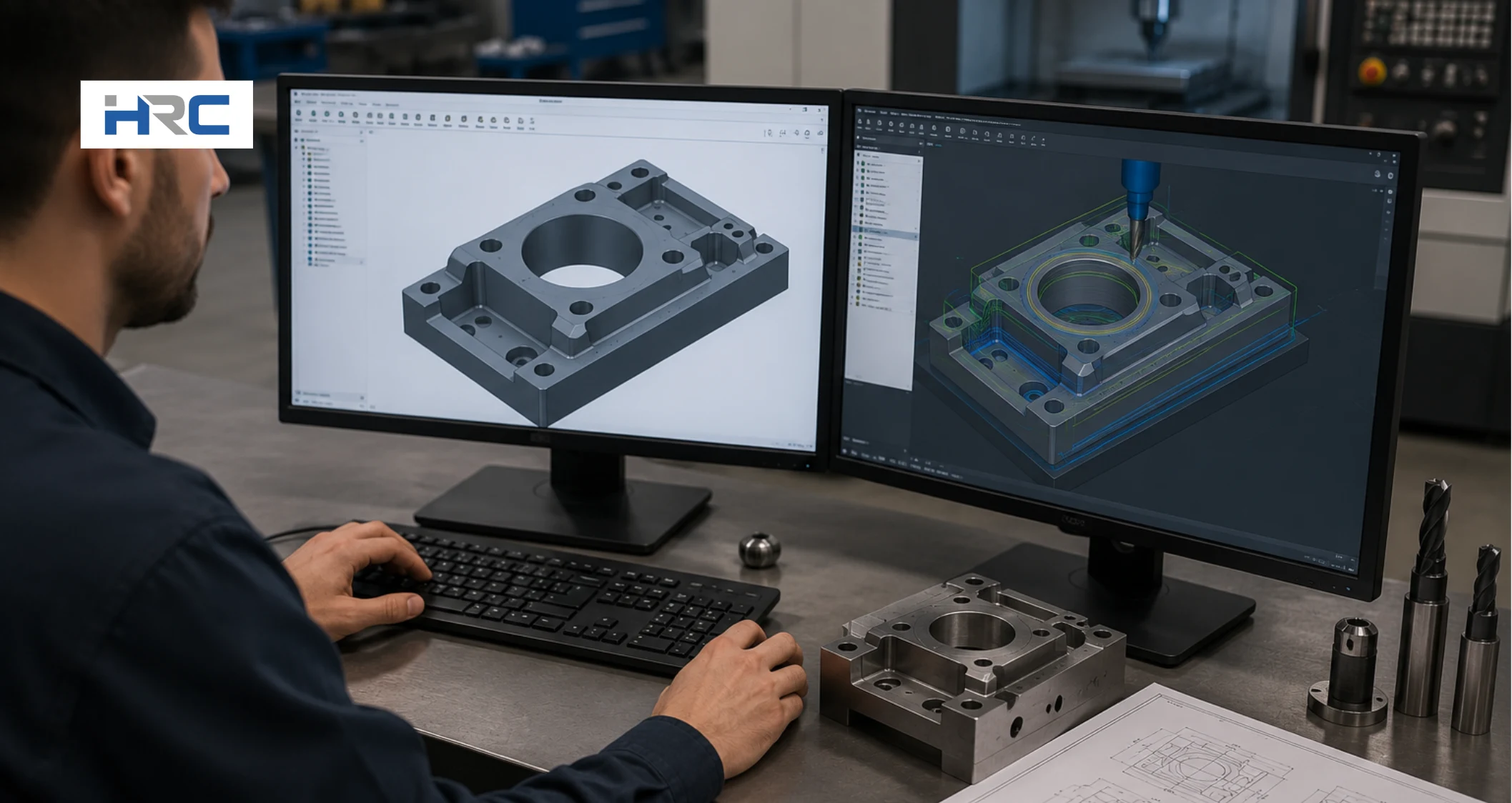
After defining the machining requirements, prepare a CAD model that will serve as the digital blueprint for the CNC machine program. Create the part in CAD software or import an existing design, then export it in a CAM-compatible format such as STEP for 3D parts or DXF for 2D profiles. Using the correct file format ensures the CAM software can accurately read the geometry and generate reliable toolpaths. If the model contains missing features, incorrect dimensions, or unsupported file formats, the programming process can be delayed or produce inaccurate machining results.
Import the CAD file into your CAM software and verify that all geometry, dimensions, and design features are displayed correctly. Many CAD/CAM platforms, such as Fusion 360, SolidWorks CAM, and Mastercam, enable a direct transition from design to manufacturing, helping maintain programming accuracy and workflow efficiency. Once the model is verified, it is ready for toolpath generation, where machining operations and cutting strategies will be defined.
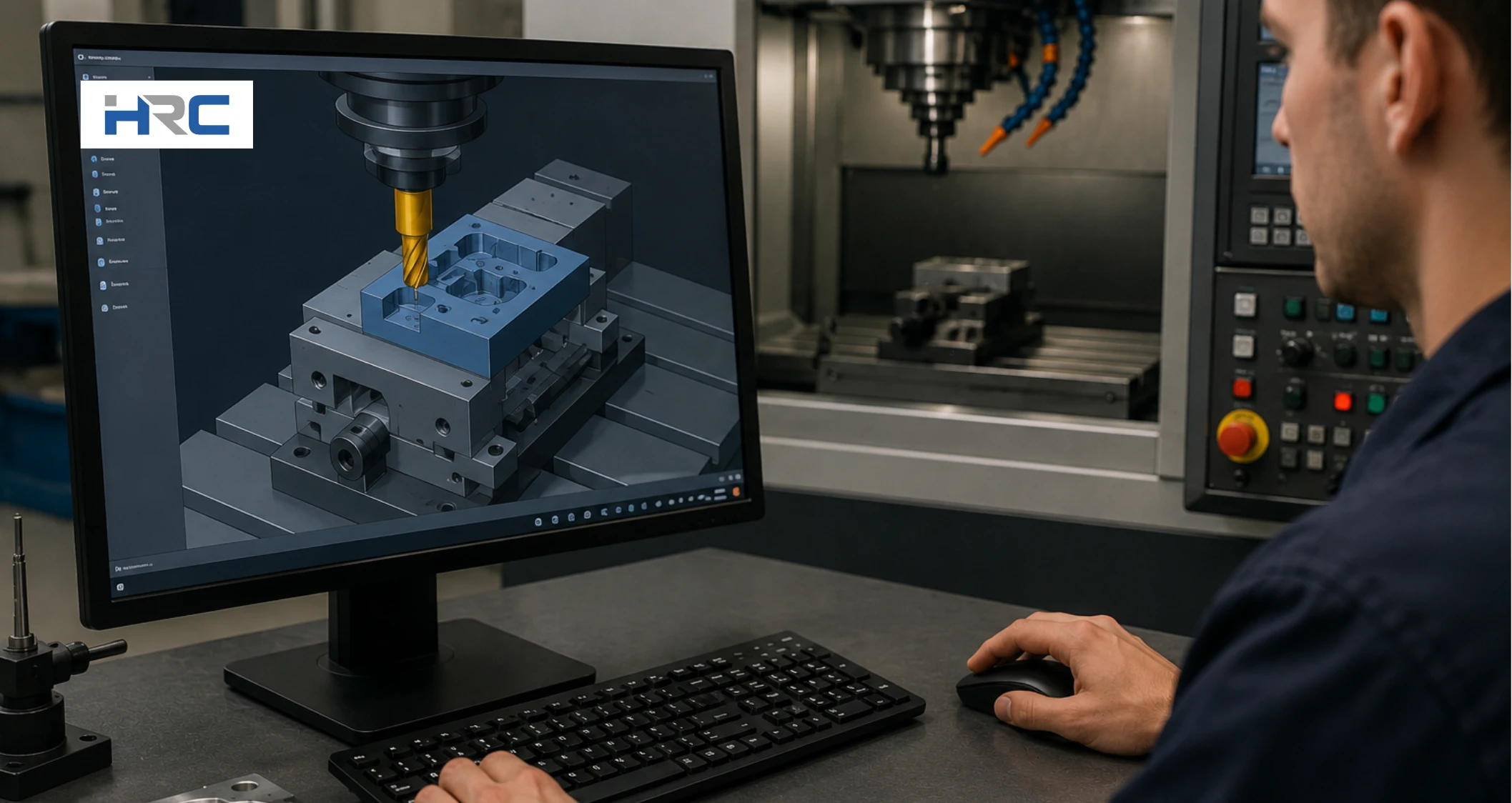
Step 3: Select CAM Software and Generate Toolpaths
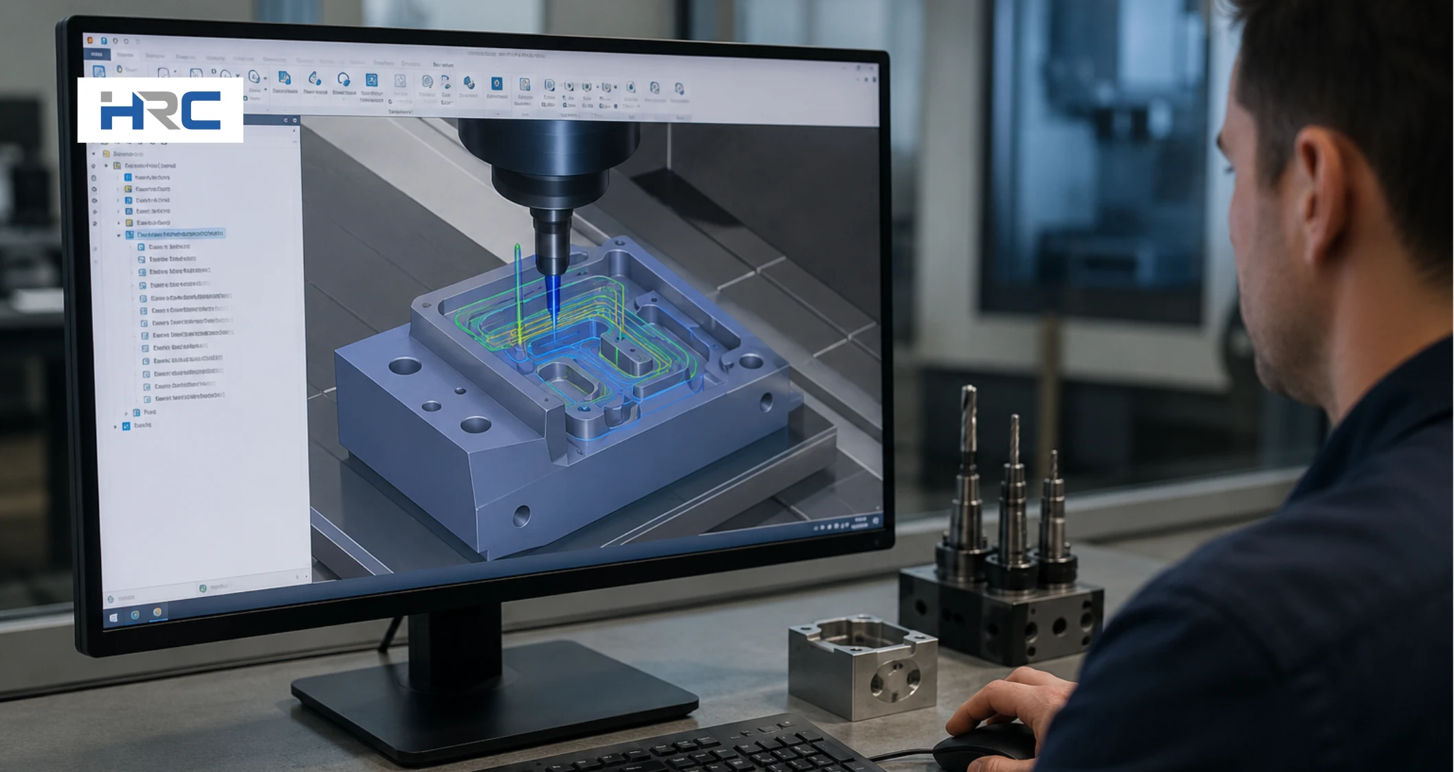
Import the verified CAD model into CAM software and select the machining operations required to produce the part. Choose a suitable CAM platform, such as Fusion 360, Mastercam, Siemens NX CAM, SolidCAM, or HyperMILL, based on the complexity of the machining operation. Define fixtures and workholding in the CAM environment to prevent collisions. Then select cutting tools, feed rates, spindle speeds, and cutting parameters according to the material, geometry, and machining requirements. Incorrect settings can increase tool wear, extend cycle time, and reduce machining accuracy.
Next, generate toolpaths that define the cutting tool’s movement for each operation. Apply roughing strategies to remove bulk material and finishing toolpaths to achieve the required dimensions and surface finish. Then verify tool clearances and simulate machining operations before post-processing the program. Finally, review all toolpaths and use a compatible post-processor to convert them into machine-ready G-code for the CNC controller.
Step 4: Choose Cutting Tools and Set Feed Rates and Speeds
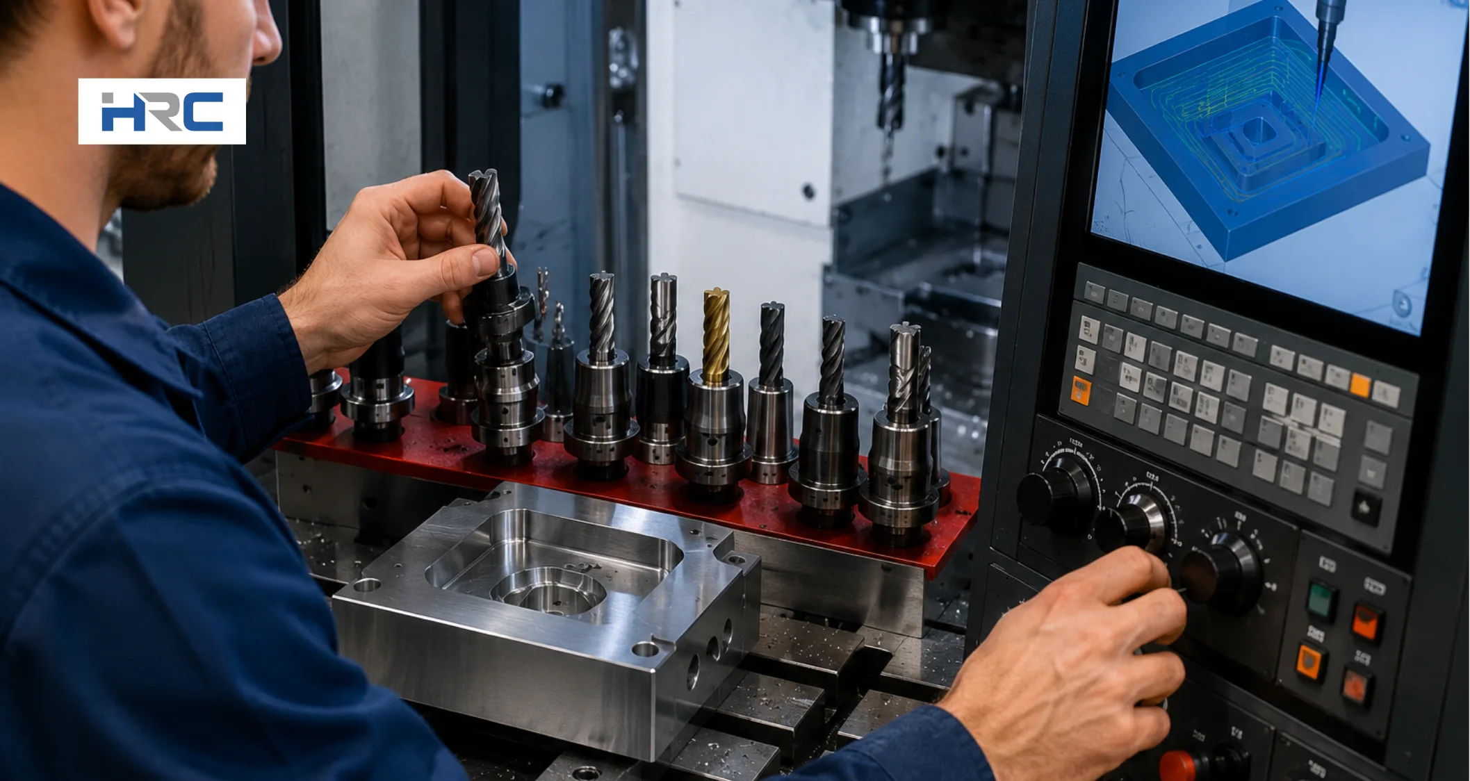
Select cutting tools based on the workpiece material, machining operation, and required part geometry. For example, aluminum requires a 2-flute carbide end mill to improve chip evacuation, while steel often benefits from a 4-flute tool for better stability and surface finish. Tool selection should also consider diameter, corner radius, flute count, and coating to ensure compatibility with machining requirements. Choosing the correct tool enhances machining accuracy, surface quality, and tool life while reducing the risk of breakage.
Next, determine spindle speed and feed rate based on material properties, tool specifications, and cutting conditions. These values can be calculated using cutting speed (Vc) and feed per tooth (fz):
RPM = (Vc × 1000) ÷ (π × Tool Diameter)
Where:
• Vc = cutting speed (m/min)
• Tool Diameter = cutter diameter (mm)
• π = 3.1416
Feed Rate = RPM × Number of Flutes × fz
• fz = feed per tooth (mm/tooth)
Start with the tool manufacturer’s recommended values and adjust as needed. Proper speed and feed settings improve tool life, machining efficiency, and finished part quality.
Step 5: Write or Generate the CNC Machine Code
Generate the CNC machine code after finalizing the toolpaths and machining parameters. The most common method is to use CAM software, which converts toolpaths into machine-ready G-code through a controller-specific post-processor. This approach improves programming accuracy and ensures the CNC program matches the requirements of the machine controller. For simple operations, you can also use conversational programming, where the controller generates code from user-entered machining parameters. Manual CNC programming remains useful for basic parts, troubleshooting, and code modifications.
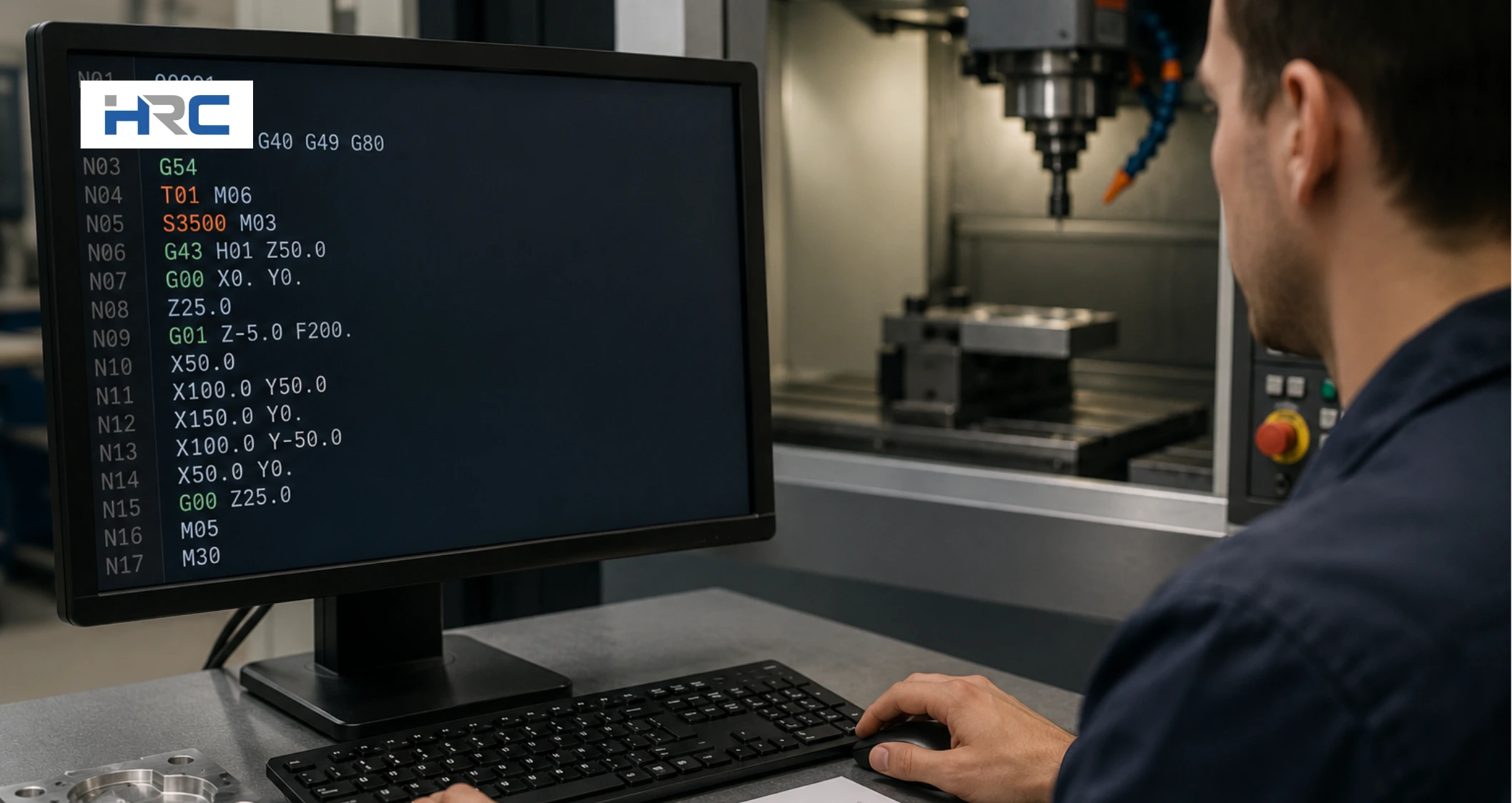
Review the generated CNC program before moving to the next stage. A typical program includes setup commands, tool calls, spindle speed commands (S-code), feed rate commands (F-code), machine functions (M-code), and tool movement instructions (G-code). Verify that the code reflects the intended machining sequence and toolpath strategy. Accurate CNC programming helps prevent machining errors, supports safe machine operation, and produces a finished part that meets dimensional and surface finish requirements.
Example of a Basic CNC Program
%
O1001
G21 G17 G90
T1 M06
S3000 M03
G54
G00 X0 Y0
G43 H01 Z50
G01 Z-5 F200
G01 X50 F500
G00 Z50
M30
%
What the code does:
- G21 = Metric units
- G17 = XY plane selection
- G90 = Absolute programming
- M06 = Tool change
- M03 = Spindle clockwise
- G54 = Work offset
- M30 = End program
Step 6: Simulate the Program and Check for Collisions or Errors
Simulate the CNC program before running it on the machine to verify toolpath accuracy and identify potential problems. Visualize material removal and review the movement of cutting tools, toolholders, and fixtures using the CAM software simulation. Check for collisions, gouging, excessive tool travel, and machining errors that could damage the part or machine. Correct any issues before generating the final CNC program.
After completing the CAM simulation, perform a controller simulation or dry run on the CNC machine without cutting material. Verify the machining sequence, tool changes, coordinate positions, and tool movements under actual machine conditions. This step helps detect errors that may not appear in the CAM environment and confirms that the program will run safely. Thorough simulation improves toolpath reliability, reduces setup risk, and helps produce an accurate finished part on the first machining attempt.
Step 7: Configure Work Offsets and the Coordinate System
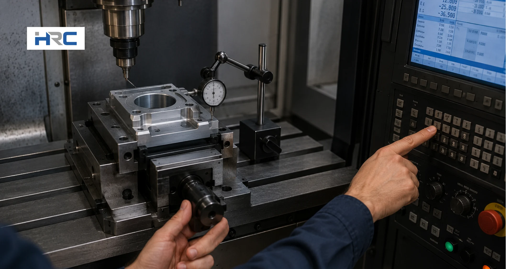
Configure the work offset and coordinate system to align the CNC program with the workpiece’s physical location. Secure the material and select a consistent reference point for part zero (X0, Y0, Z0), such as a stock corner or the fixed jaw of a vise. Then measure the position of this reference point relative to the machine coordinate system and save the values in a work offset, such as G54. This setup ensures the CNC machine interprets the toolpaths from the correct location.
Verify that the selected work offset matches the coordinate system used in the CNC program. Check all X-axis, Y-axis, and Z-axis positions before machining begins. Incorrect work offsets can cause dimensional errors, missed features, or tool collisions. Proper coordinate system configuration creates a stable and repeatable setup, improves machining accuracy, and ensures the finished part matches the intended design.
Step 8: Load the Program and Run a Test Cut
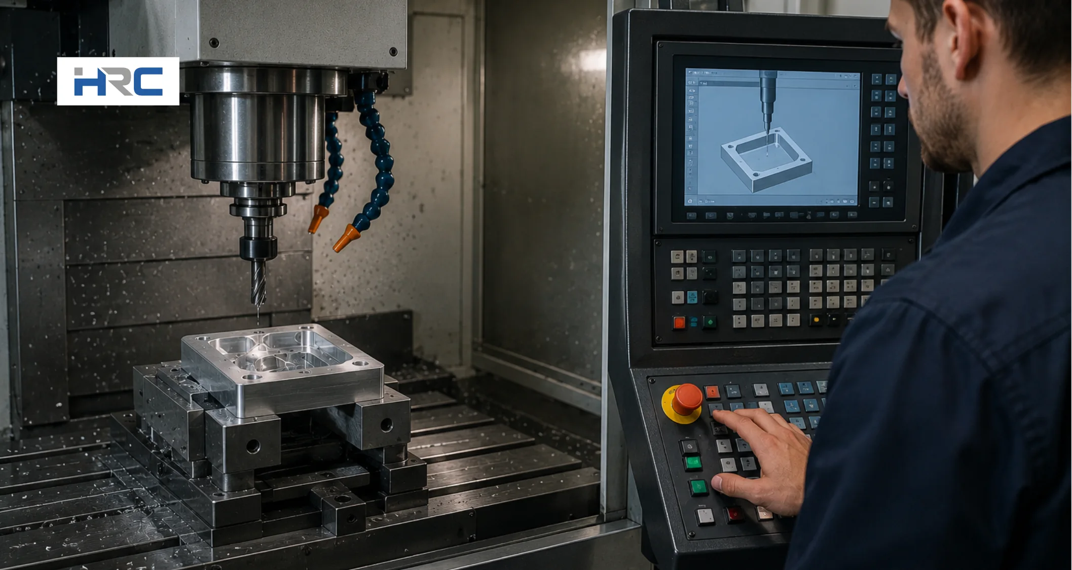
Load the CNC program into the machine controller and verify that the correct part program, work offset, and tool offsets are active. Before machining begins, clear the workspace and confirm that all fixtures, clamps, and tools are positioned safely. Then perform a dry run or air cut, allowing the machine to follow the programmed toolpaths without cutting material. This step helps verify tool movement, machining sequence, and program accuracy while identifying potential collisions or setup errors.
After completing the dry run, start the machining operation using conservative feed rates and spindle speeds. Monitor the machine closely during the first test cut and check for unexpected tool movement, vibration, or cutting issues. If any problems appear, stop the program and make the necessary corrections before continuing. Running a test cut improves machine safety, reduces the risk of scrap, and confirms that the CNC program can produce the finished part as intended.
Step 9: Inspect the Machined Part and Refine the Program
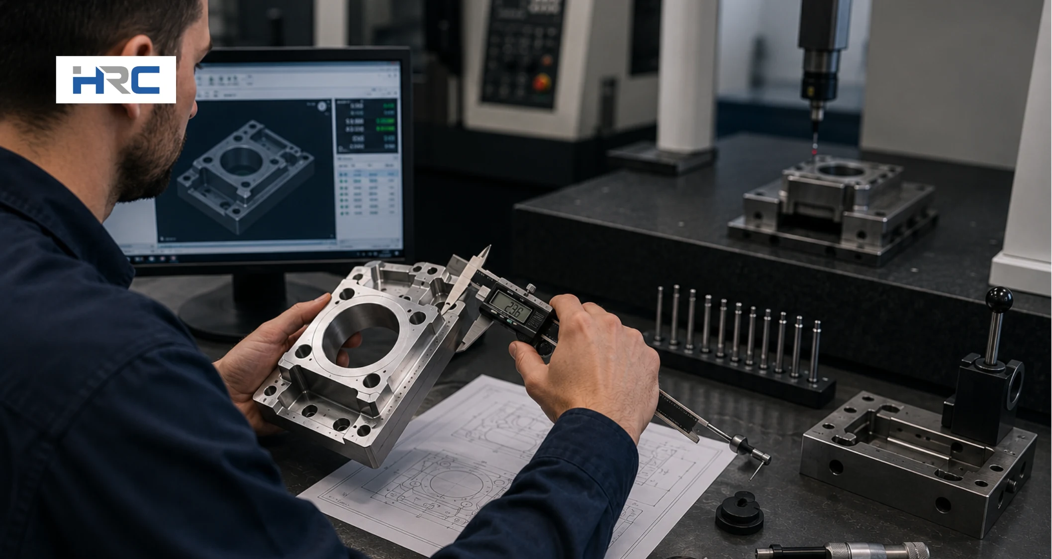
Inspect the machined part after the test cut to verify that it matches the dimensions, tolerances, and surface finish requirements defined in the part drawing. Visually examine the component to detect defects, missing features, or surface imperfections. Then measure critical dimensions using inspection tools such as calipers, micrometers, or gauges. Comparing the finished part against the design specifications helps confirm machining accuracy and reveals any areas that require correction.
Use the inspection results to refine the CNC program, tool offsets, feed rates, or machining strategy as needed. For high-precision parts, consider using on-machine probing or a coordinate measuring machine (CMM) to verify geometric accuracy and collect detailed measurement data. Continuous inspection and program refinement improve part quality, reduce scrap, and create a more reliable CNC machine programming process for future production runs.
What Are the Main CNC Programming Methods?
The main CNC programming methods are manual, CAM, and conversational programming. Manual programming provides direct code control, CAM software automates toolpath generation from CAD models, and conversational programming generates code through guided machine prompts. The best method depends on part complexity, production volume, programming experience, and machining requirements.
Below are the 3 main CNC programming methods:
- Manual CNC Programming
- CAM CNC Programming
- Conversational CNC Programming
Manual CNC Programming
Manual CNC programming involves writing G-code and M-code line by line without CAM software. The programmer enters every instruction directly into the CNC controller, giving complete control over tool movement and machining operations. It works best for simple parts, quick edits, and troubleshooting. The method is difficult to apply to complex geometries and increases the risk of error. One of the simplest CNC programming examples is G00 X0 Y0, which moves the tool quickly to the start point. G01 X50 Y0 F150 then moves it in a straight line to X50 at a feed rate of 150, creating a straight cut along the X-axis.
CAM CNC Programming
CAM CNC programming uses CAD/CAM software to automatically convert a CAD model into machine-ready code. After defining stock material, tools, and machining operations, the software generates optimized toolpaths and outputs G-code through a post-processor. It is ideal for complex parts and high-precision manufacturing. While highly efficient, it requires software knowledge and setup experience. Common CNC programming examples include CAM-generated contouring, pocketing, and multi-axis milling toolpaths.
Conversational CNC Programming
Instead of writing code manually, conversational CNC programming uses machine-based prompts to create the program. The operator selects an operation, enters dimensions, speeds, depths, and tool information, and the controller automatically generates the required code. This method suits simple machining tasks, prototypes, and shop-floor adjustments. It is easy to learn but limited to advanced geometries. CNC programming is commonly used for tasks such as facing surfaces, drilling bolt-hole patterns, and milling rectangular pockets.
What Factors Affect CNC Machine Programming?
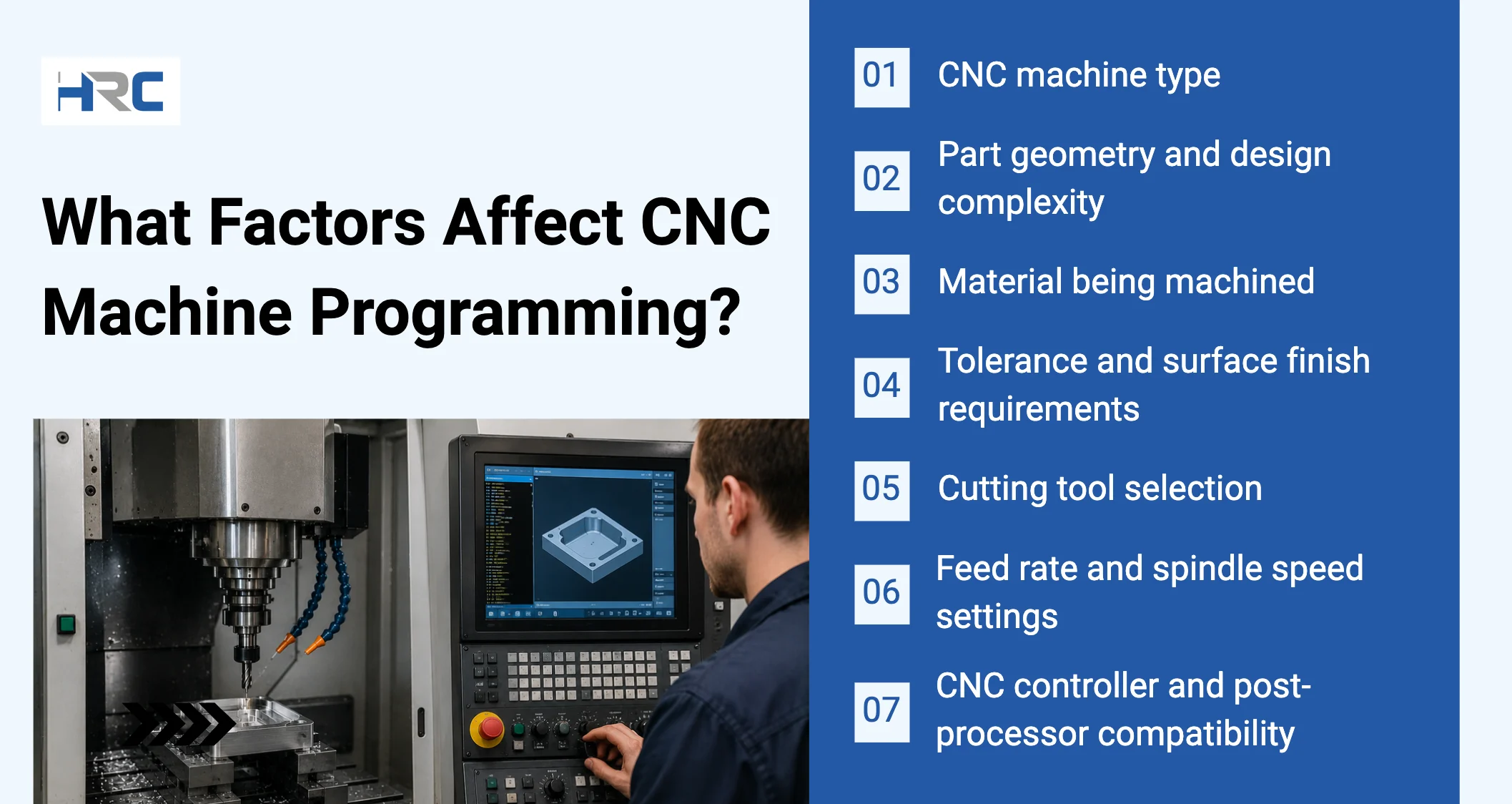
The main factors that affect CNC machine programming are CNC machine type, part geometry and design complexity, material being machined, tolerance and surface finish requirements, cutting tool selection, feed rate and spindle speed settings, and CNC controller compatibility. Each factor influences toolpath strategy, code output, setup risk, machining accuracy, cycle time, and first-part inspection. Understanding these variables helps create reliable CNC programs and consistent machining results.
7 common factors affecting CNC machine programming are:
- CNC machine type
- Part geometry and design complexity
- Material being machined
- Tolerance and surface finish requirements
- Cutting tool selection
- Feed rate and spindle speed settings
- CNC controller and post-processor compatibility
- CNC machine type
The type of CNC machine determines how toolpaths are created and how the CNC program controls movement. CNC mills, lathes, and routers require different code structures, axis configurations, and machining strategies. Machine capabilities influence setup risk, machining accuracy, and cycle time. For example, a 5-axis CNC mill requires more advanced toolpaths than a 3-axis machine. First-part inspection checks that toolpaths execute correctly within machine and setup constraints. - Part geometry and design complexity
The geometry of a part plays a critical role in CNC machining, influencing both toolpath strategy and program complexity. Simple features may require basic toolpaths, while complex surfaces, deep pockets, and multi-sided parts often need advanced CAM-generated machining strategies. Higher part complexity increases setup risk and cycle time and requires more detailed programming, as well as stricter first-part inspection. - Material being machined
The material selected for a CNC machining operation significantly influences cutting parameters, toolpath decisions, and overall machining efficiency. Hard materials such as stainless steel require more conservative cutting parameters and toolpaths, while aluminum generally allows higher cutting speeds and feed rates. Material characteristics affect stability, accuracy, tool wear, and cycle time, with first-part inspection ensuring correct dimensions and surface finish. - Cutting tool selection
Cutting tool selection plays a critical role in CNC machining, affecting toolpath design, machining efficiency, and program reliability. Tool diameter, flute count, geometry, and material influence cutting performance and machining parameters. Proper tool selection reduces setup risk, improves machining accuracy, and shortens cycle time. Incorrect tooling may lead to deflection, poor finish, and dimensional errors, with first-part inspection verifying correct tool performance and quality. - Feed rate and spindle speed settings
Feed rate and spindle speed settings control how aggressively material is removed during machining. These parameters directly influence toolpath performance, code output, cycle time, and machining accuracy. Excessive values can increase tool wear or create surface defects, while conservative settings may reduce productivity. Proper calculations improve cutting stability and part quality, while first-part inspection verifies dimensions, tool condition, and surface finish. - Tolerance and surface finish requirements
Tolerance and surface finish requirements determine how precise the CNC program must be. Tight tolerances often require smaller step-overs, finishing passes, and smoother toolpaths to maintain accuracy. These requirements increase cycle time and demand more stable setups. The code output may include additional machining operations to achieve the specified finish quality. First-part inspection focuses on verifying dimensions, geometric accuracy, and required surface roughness values. - CNC controller and post-processor compatibility
CNC controller and post-processor compatibility ensures that CAM-generated toolpaths are correctly translated into machine-readable code. Different controllers may interpret commands, tool changes, and canned cycles differently. Incompatibility can lead to setup risks, code errors, and machining inaccuracies. Correct post-processor selection improves program reliability and reduces troubleshooting time, while first-part inspection confirms accurate code execution.
What are the Best CNC Programming Tips for Beginners?
The best CNC programming tips for beginners are learning basic G-code and M-code, starting with simple geometry, maintaining clear setup documentation, following safe tool clearance practices, checking controller-specific code, using version control, reviewing first-part inspection results, and staying prepared to use the emergency stop. These habits improve programming accuracy, reduce setup risk, prevent machining errors, and build confidence when learning how to program a CNC machine.
The best CNC programming tips for beginners are:
- Basic G-code and M-code awareness
Learn the purpose of common G-codes and M-codes before creating CNC programs. G-codes control tool movement, while M-codes control machine functions such as spindle and coolant operation. Understanding these commands helps reduce programming mistakes, improves code review, and supports safer machining. Regular practice with basic CNC programming code builds confidence and troubleshooting skills. - Simple geometry before complex parts
Start with simple shapes such as rectangles, circles, and basic pockets before programming advanced components. Simple geometry helps you understand coordinates, tool movement, and machining logic without unnecessary complexity. This approach improves programming accuracy, reduces setup risk, and makes troubleshooting easier when learning CNC machining basics and toolpath development. - Clear setup documentation
Create detailed setup records for every CNC program. Document work offsets, tool numbers, cutting tools, feed rates, spindle speeds, and fixture locations. Clear documentation improves setup consistency, simplifies program verification, and reduces the risk of machining errors. Maintaining organized records also helps refine CNC machine programming for future production runs. - Safe tool clearance habits
Always program safe retract moves and verify clearance above the workpiece, fixtures, and clamps. Establish a repeatable safe position before rapid tool movements and tool changes. Consistent clearance practices reduce collision risk, protect cutting tools, and improve machining reliability. Running simulations and air cuts helps confirm safe tool movement before machining begins. - Controller-specific code checking
Review the CNC program to ensure it meets the machine controller’s requirements. Different controllers may interpret G-code, M-code, and canned cycles differently. Verify post-processor settings, safety commands, and controller syntax before machining. Controller-specific code checks improve program reliability, reduce setup issues, and prevent machine-related programming errors. - Version control for program edits
Save program revisions systematically instead of overwriting previous versions. Maintaining revision history allows you to compare changes, restore approved programs, and track modifications accurately. Good version control reduces the risk of using outdated code, improves troubleshooting, and creates a more reliable CNC programming process across multiple production runs. - First-part inspection feedback
Inspect the first machined part carefully and compare all critical dimensions against the part drawing. Use the results to adjust tool offsets, machining parameters, or toolpaths when necessary. First-part inspection validates the CNC program and setup, improves machining accuracy, and helps prevent recurring errors throughout the remainder of the production cycle. - Emergency stop readiness
Know the location and operation of the emergency stop button before running any CNC program. Verify that it remains accessible during setup and machining. Emergency stop readiness allows a quick response to unexpected machine behavior, reducing the risk of tool damage, machine crashes, and safety incidents during CNC machining operations.